FARO Gage
May 2011
12
Chapter 2: Setup
CAUTION: Do not hold the Gage except in the button area when installing a
probe. Holding the Gage at the last joint may stress the tube and damage the
system.
2 Rotate the probe clockwise and thread the probe into the Gage.
3 Use the 12mm wrench to hand-tighten the probe.
CAUTION: Only hand-tighten the probe with the 12mm wrench. Do not
over-tighten the probe.
Use your measuring software to setup and compensate the probe. See “Probes”
on page 54.
FARO Gage Power Supply
Power the Gage with the supplied power supply. The power supply shall be
NRTL Listed for US and Canada. For IEC member countries and Europe, the
power supply must be certified for the country in which the equipment is sold.
Contact FARO’s Customer Service to order a replacement. All servicing should
be referred to qualified service personnel.
CAUTION
(INDOOR USE ONLY)
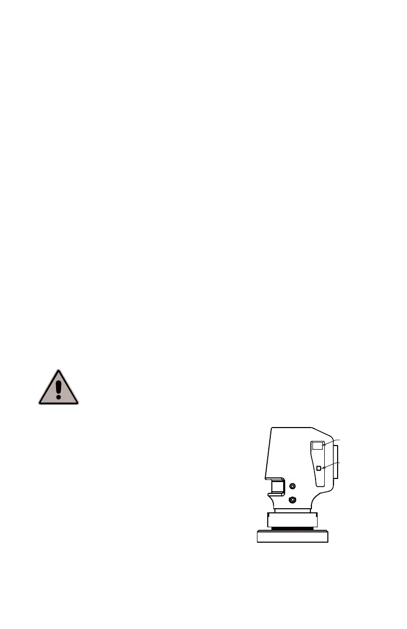
Supplying Power to the FARO Gage
Place the Gage in an area with a properly grounded
outlet receptacle. The On/Off switch disconnects
power from the Gage.
WARNING: Do not disconnect, or isolate, the
Ground pin on the power supply cord.
Select the proper power supply cord intended for
installation in a protected environment. The power
supply automatically adjusts to the voltage.
• For 120V Connection: Use a UL Listed, type SJT
or SVT, 3-Conductor, 18 A.W.G. power supply cord, terminating in a molded-
on plug cap rated 125 VAC, 15A minimum, with a minimum length of six feet.
Rated Voltage: 110 - 240V ~ 50 - 60 Hz
Voltage Tolerance: +10% or -10%
Rated Input: 0.8A
Sec. Voltage: +12 VDC
Sec. Current: 2A
Pollution Category: 2
Installation Category: 2
08M47E00_FAROGage.book Page 12 Wednesday, June 8, 2011 4:12 PM