FARO Gage
May 2011
15
Chapter 3: Operation
Chapter 3: Operation
This chapter describes the controls, visual indicators, and advanced connection
options for the Gage. Make sure that you have read the setup instructions and
setup your Gage properly. For more information, see “Setup” on page 7.
Numerical and Signal Processing
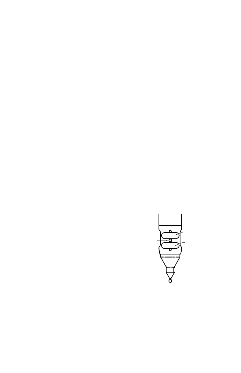
The Gage includes a complete electronics system located within the body of the
Gage. Signals from each joint are processed and positional data is sent out to the
computer.
The Gage includes a complete electronics system located within the body of the
Gage. Signals from each joint are processed and positional data is sent out to the
computer.
N
OTE: The Gage electronics go into standby mode, or turn off, after two hours
of no encoder movement. Move the Gage to exit standby mode and reference
the encoders to continue measuring. See “Referencing the Encoders” on
page 17.
This hardware option is enabled/disabled in the H
ARDWARE CONFIGURATION
dialog box. For more information, see “Hardware Configuration” on page 53.
Handle LED
After applying power to the Gage, the LED is
SOLID GREEN while an internal startup check
runs. After this is complete, the LED indicates the
following:
• FLASHING RED - if the Gage successfully
communicates with the computer, and the
encoders are not referenced. See “Referencing
the Encoders” on page 17.
• OFF - if the Gage successfully communicates
with the computer, and the encoders are
referenced. See “Referencing the Encoders” on page 17.
• SOLID GREEN - if the Gage successfully communicates with the computer,
and the encoders are referenced - Renishaw Probe only. See “Renishaw Probe
Installation and Operation” on page 27.
LED
BACK BUTTON
FRONT BUTTON
08M47E00_FAROGage.book Page 15 Wednesday, June 8, 2011 4:12 PM