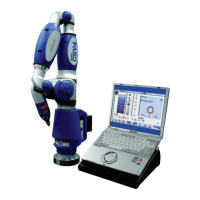
FARO Gage
May 2011
26
Chapter 4: Probes
Custom Probes
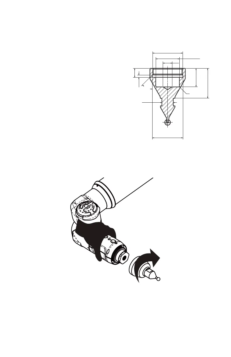
You may create any size probe to attach to
the Gage.
• The probe thread size is 1¼-20 UN THD.
• The base of the probe should follow the
shape of the FARO probes.
Your custom probe should be a rigid as
possible. Any deflection in the probe will
add inaccuracy to the Gage system.
N
OTE: FARO Technologies Inc. does not
guarantee the accuracy of the Gage with
the use of a custom probe.
Installing Probes
The probe attaches to the threaded handle at the end of the Gage. Use the 12mm
wrench in the Probe Case to install the probe.
• Hold the button area near the end of the Gage with one hand.
CAUTION: Do not hold the Gage except in the button area when installing a
probe. Holding the Gage at the last joint may bend the tube and damage the
system.
• Rotate the probe clockwise and thread the probe into the Gage.
Figure 4-1 Installing a Probe
1¼-20 THD
11.85
R 0.5
19.5
ø
ø10
MAX
25.1
24.9
ø
32.4
32.2
62˚
28˚
31.6
31.4
9.6
9.4
2.6
2.4
08M47E00_FAROGage.book Page 26 Wednesday, June 8, 2011 4:12 PM