FARO Gage
May 2011
55
Chapter 7: Configuring the FARO Gage in CAM2 Gage
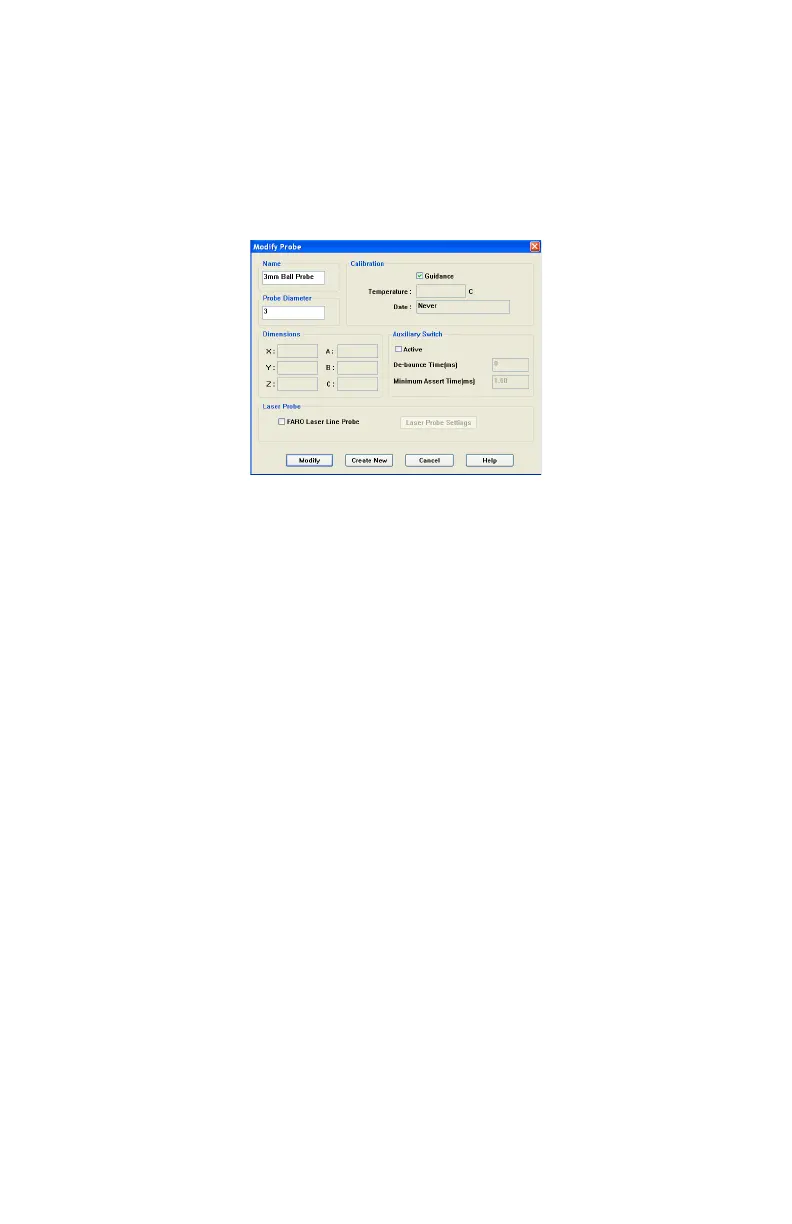
Edit Probe
Click the EDIT button in the COMPENSATION dialog box to modify the details of
the current probe. Change any settings and click the MODIFY button to
continue.
To create a new probe:
1 Enter a new Name for the probe.
2 Enter the diameter of the probe. Check the status bar at the bottom of your
screen for the current units.
3 Select the A
UXILIARY SWITCH check box, and enter a De-bounce Time if
necessary.
4 Select the G
UIDANCE check box to use the guidance feature in hole
compensation. See “Hole Method - Guidance” on page 57, and “Hole
Method” on page 60.
5 Click the CREATE NEW button.
The new probe is now current. You must compensate the new probe.
Probe Compensation Overview
Probe compensation is a localized process by which a measurement device is
optimized to perform measurements accurately.
To understand probe compensation, you must first understand the Gage's
reference system. The Gage is factory compensated from the base to the last joint
or axis, and the position of this joint is defined by the coordinate system which
originates at the base of the Gage. The last axis of the Gage has its own
coordinate system, and the location of the center of the ball probe is reported in
the probe's coordinate system. After the probe's coordinates are established, these
Figure 7-2 Modify Probe dialog box
08M47E00_FAROGage.book Page 55 Wednesday, June 8, 2011 4:12 PM