A. Technical appendix
A-20
Festo P.BE-CB-COMP-EN en 1102d
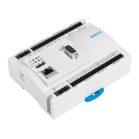
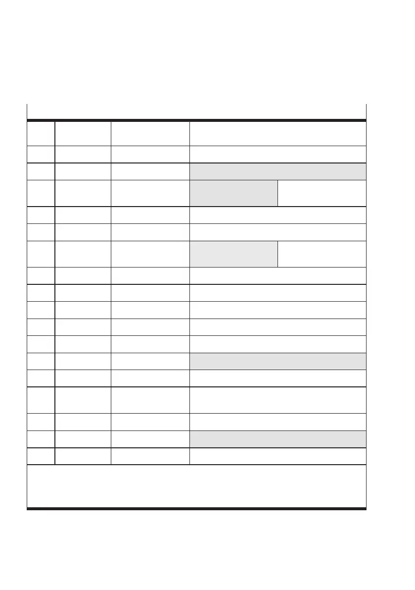
PLC connector socket
O/7 Blue OUT24_PLC_Power Reference voltage +24 V DC
(signal level after Boot procedure = HIGH)
O/8 Red OUT24_ Feeder Controlling the small parts conveyor
I/9 Black IN24_Cam_Enable External camera trigger
1)
I/10 Purple IN24_Ext_Sensor External sensor
1) 2)
External type selection:
Bit 3
I/11 Grey/pink IN24_Key_Inhibit Button lock
I/12 Red/blue IN24_Jam1 Bufferzonesensor1
I/13 White/green IN24_Jam2 Buffer zone
Sensor 2
1)
External type selection:
Bit 2
O/14 Brown/green OUT_PWM Do not connect
I/15 White/yellow IN24_Ext_Teach Select Teach mode / next orientation
3)
O/16 Yellow/brown OUT24_Res2 Unused
O/17 White/grey OUT24_Error Fault status 1: Status signal “Fault”
I/18 Grey/brown IN24_Counter-Rst Start new counting cycle
I/19 White/pink IN24_Ext-Fault External fault E 01
1)
I/20 Pink/brown I N24_TypeSel0 External type selection: Bit 0
O/21 White/blue OUT24_BOX_READY 24 V DC reference voltage for buffer zone sensor /
Ready to operate / Control conveyor device
O/22 Brown/blue OUT24_Counte r-fin Target number reached
O/23 White/red OUT24_Warning Fault status 0: Status signal “Warning”
1)
O/24 Brown/red OUT24_Re s1 Unused
1)
Functions with a grey background have been deactivated at the fac tory and can be activated and
adapted with CheckKon.
2)
The counting function and the special function “External sensor” c annot be used at the same time.
3)
User-specific function. Consult your Festo Service if you have any problems.
Tab. A/12: PLC connector socket
 Loading...