2. Fitting and commissioning
2-7
Festo P.BE-CB-COMP-EN en 1102d
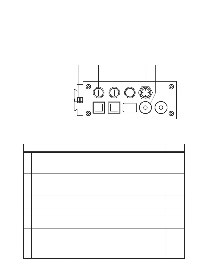
2.3 Electrical connection
1
FE
2 ACTUA TORS
3 BUFFER/FEEDER
4 DIAG
5 24 V DC
6 ENCODER
7 PLC
1234567
Fig. 2/4: Connections of the Checkbox
Function
Chapter
1 – Functional ear th connection 2.3
2 – Connection of a maximum of 3 actuators for sor t ing out the tested conveyed
parts
3.2
3 – Connection of 1 buffer zone sensor for controlling the transfer of work items to
the next machine
– 24 V po wer out puts fo r controlling the supply system (small parts conveyor) and
the transpor t ing system (conveyor device)
3.3
4 – Connection of a diagnostic PC for system diagnosis, visualizing and optimizing
the test procedure with the software packages CheckKon and CheckOpti
3.4
5 – Connection of the 24 V DC power supply 2.3
6 – Connection of a rotary pulse generator for determining the speed of the conveyor
system with increased demands for length ac c uracy
3.5
7 – Connection of 2 buffer zone sensors for controlling the transfer of work items to
the next machine
– 24 V po wer out put f or controlling the supply system (small parts conveyor) and
the transpor t ing system (conveyor device)
– I/O signals for process monitoring and higher-order control or for controlling a
downstream-switched machine.
3.6