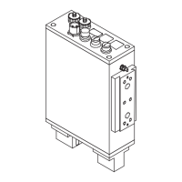
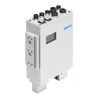
3. The I/O module
3-14
Festo P.BE-CB-COMP-EN en 1102d
3.6 PLC
Observe the following when connecting a higher-order con-
troller:
S Use the PLC cable with 24-pin Binder plug supplied.
S Connect the cables of the PLC according to the cable
assignment in Appendix A.4.
S Make sure that the maximum sum current of 1 A at the
PLC connection is not exceeded.
Reference voltage The reference voltage is available at pin 4 (GND) and pin O/7
(+24 V). Fuse: 700 mA, automatic reset.
Pin Reference voltage
4 0V
e.g. as reference potential for the PLC/reference voltage fo r
buffer zone sensors
O/7 +24 V DC
e.g. as voltage supply for opto-isolated PLC I/O module,
signal level after boot procedure = HIGH
Tab. 3/3: Reference voltage
Load voltage Consuming devices can be supplied with power via pin 4
(GND) and pin O/7 (+24 V) under the follo wing conditions:
S Connect only consuming devices which return the com-
plete current to the CHB-C-X. In this way you can prevent
asymmetries of the currents in the outgoing and return
lines from reducing the effect of the filter.
S Load output O/7 with maximum 700 mA.