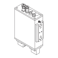
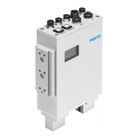
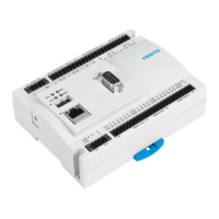
3. The I/O module
3-3
Festo P.BE-CB-COMP-EN en 1102d
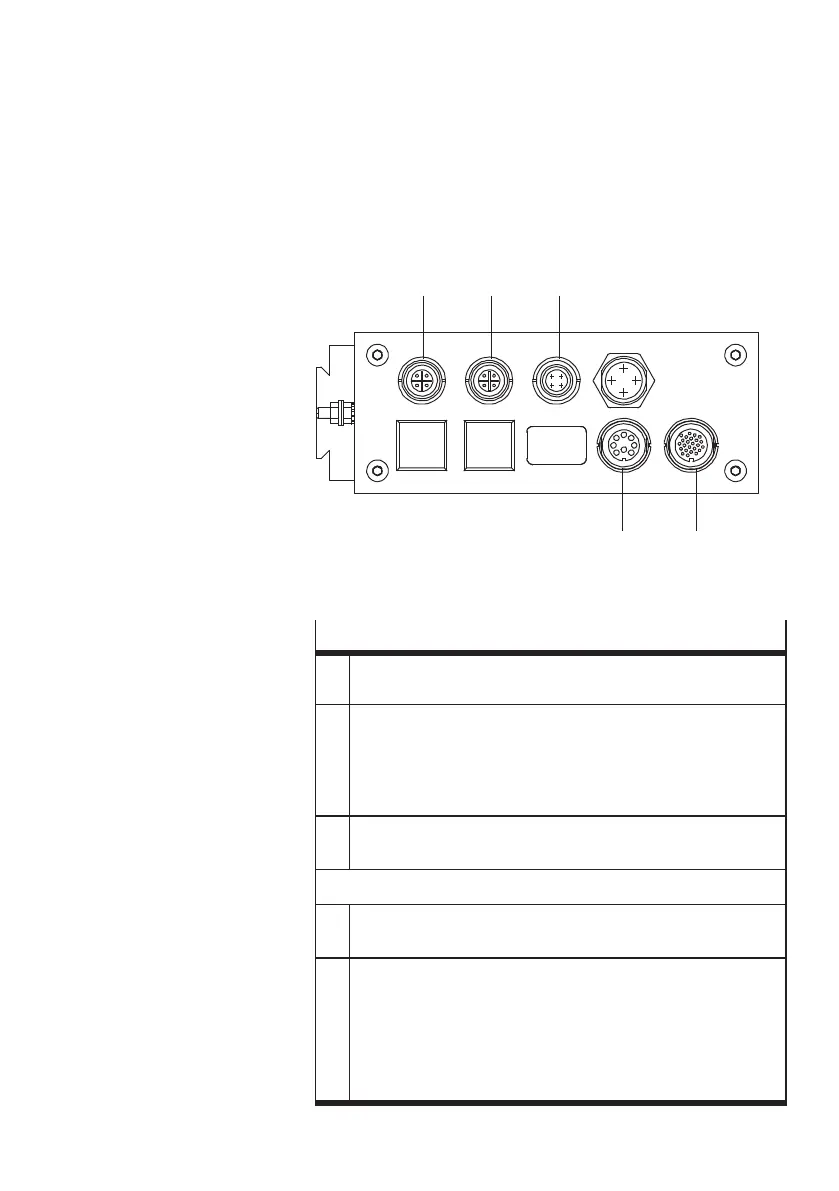
3.1 Interfaces
1
ACTUA TORS
2 BUFF ER/F EEDER
3 DIAG
4 ENCODER
5 PLC
45
123
Fig. 3/1: The I/O module of the CHB-C-X
Function
1 – Connecting a maximum of 3 actuators for sor ting out the
tested conveyed par ts
1)
2 – Connection of 1 buffer zone sensor for controlling the
transfer of work items to the next machine
– 24 V po wer out puts fo r controlling the supply system
(small parts c onveyor) and the transpor ting system
(conveyor device)
1)
3 – Connection of a diagnostic PC for system diagnosis,
visualizing and optimizing the test procedure
1)
The connection is wired internally with the PLC connection
4 – Connection of a rotary pulse generator for determining the
speed of the conveyor system
5 – Connection of 2 buffer zone sensors for controlling the
transfer of work items to the next machine
– 24 V po wer out put f or controlling the supply system
(small parts c onveyor) and the transpor ting system
(conveyor device)
– I/O signals for process monitoring and higher-order control
or for controlling a downstream-switched machine.