3. The I/O module
3-10
Festo P.BE-CB-COMP-EN en 1102d
3.4 DIAG
Note
In the diagnostic mode the CHB-C-X transmits additional
information via the diagnostic interface. During the trans-
mission time no par ts are checked.
• Use the DIAG connection only for commissioning and for
servicing.
• Do not operate the CHB-C-X in the diagnostic mode with
the full parts rate. In this way you can prevent parts
from passing the actuator positions unchecked.
In order to connect a diagnostic PC use cable KDI-SB202-BU9
(see Appendix A.6 Accessories).
1. Connect the diagnostic cable to the followi ng connections:
– the diagnostic interface DIAG on the CHB-C-X
– a serial interface (COM) of the diagnostic PC
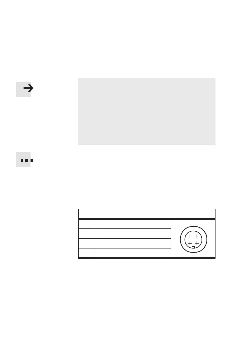
DIAG connector socket
I/1 Received data
1
43
2
O/2 Transmitted data
3 Data GND
4 Screened
2. Start CheckKon or CheckOpti in order to display the
system data and to set the system parameters in the
Teach or test modes.
3. Conclude CheckKo n and CheckOpti when you have
undertaken the necessary settings.