Festo Controller CECC
13
3.5.2 CANopen X6
The controller CECC has a CANopen interface with CANopen master functionality for connecting
CANopen slaves.
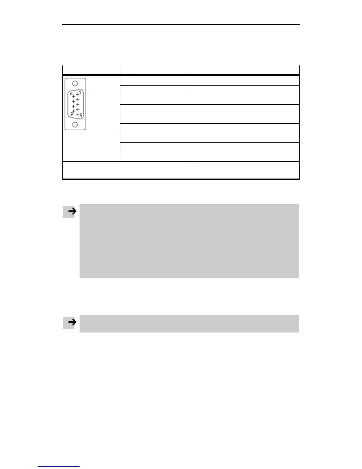
The CANopen interface is designed as a 9-pin Sub-D plug.
CAN bus plug Pin Signal Comment
1 n.c. Not connected
2 CAN_L
1)
CAN Low
3 CAN_GND CAN Ground
4 n.c. Not connected
5 CAN_SHLD Connection to functional earth
6 CAN_GND CAN Ground (optional)
7 CAN_H
1)
CAN High
8 n.c. Not connected
9 n.c. Not connected
1) If the CECC is at the end of the cable:
• Connect pin 2 and pin 7 using a terminating resistor (120 ohms/0.25 W).
Table: Pin allocation of the CANopen interface
Connecting CANopen slaves
Note
If installation has not been carried out correctly and if high baud rates are used, data transmission
errors may occur as a result of signal reflections and attenuations.
Causes of transmission faults may be:
– No terminating resistor between CAN_L (pin 2) and CAN_H (pin 7) Table Pin allocation of
the CANopen interface
– Incorrect screened connection
– Branches
– Long distances
– Unsuitable cables
• Use a twisted, screened 2-wire cable for the CANopen bus.
• Connect the housing of the CAN bus plug to FE via CAN_SHLD (pin 5).
In the case of a motor controller with external power supply:
• Make sure that CAN_GND (pin 6) on the CECC is not used.
Note
CANopen slaves at the CANopen interface of the CECC are not supplied with power.