Festo Controller CECC
17
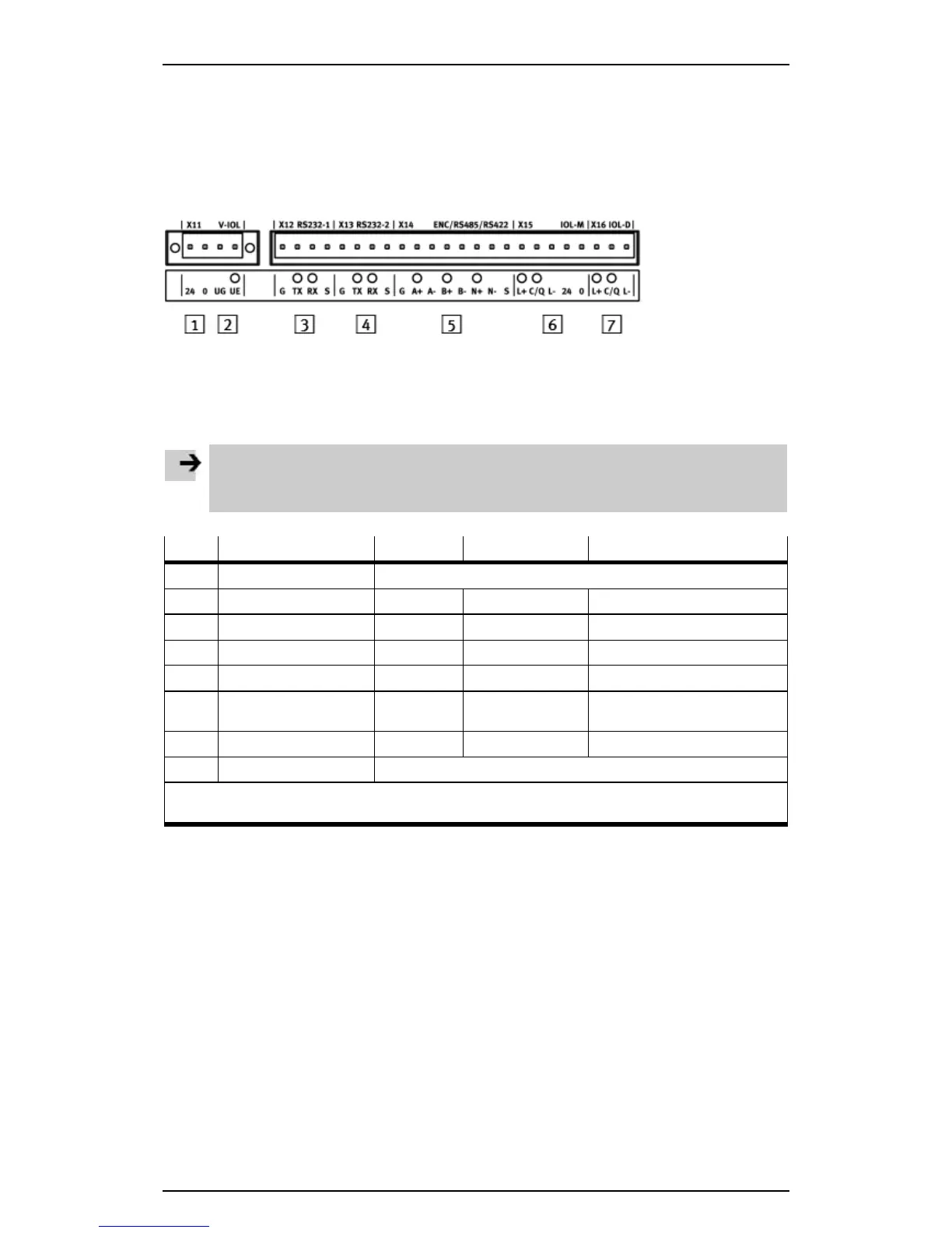
3.5.6 Encoder/RS422/RS485 X14 (CECC-S)
The controller CECC-S has a combined interface with the following connection options:
– Encoder (ENC, RS422-based encoders only)
– RS422
– RS485
2
UG/UE power supply for external encoder (5 V, max. 100 mA) X11
5
Multiple interface ENC/RS422/RS485 X14
Figure: CECC-S, top manifold rail with multiple interface
Note
Simultaneous use of these communication interfaces is not possible.
• Configure and use the signals from one of the three interfaces only.
Pin Signal ENC RS422 RS485
X14.1 G Ground
X14.2 A+ Track A+ Transmitted data+ Transmitted/received data+
1)
X14.3
A– Track A–
Transmitted data– Transmitted/received data–
1)
X14.4 B+ Track B+ Received data+ n.c.
X14.5 B–
Track B–
Received data– n.c.
X14.6 N+ Zero track
N+
n.c. n.c.
X14.7 N–
Zero track N–
n.c. n.c.
X14.8 S Screen, connection to functional earth
1) If the CECC is the first or last station on the RS485 cable, terminate the RS485 cable with a 120 Ω
resistor at pins 14.2 and 14.3.