Festo Controller CECC
9
3.2.2 Wall mounting
The controller CECC has two holes for wall mounting.
Mounting
Note
Mounting the CECC on uneven, flexible surfaces can result in damage.
• The CECC must only be mounted on flat, torsionally rigid surfaces.
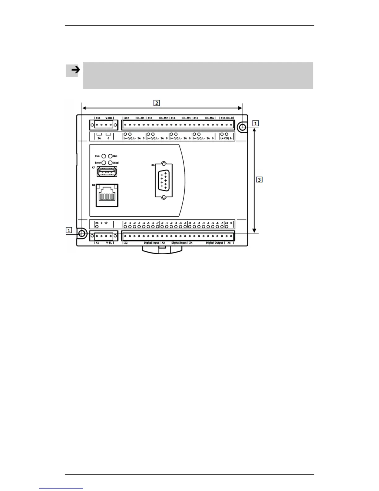
1
Mounting holes Ø 4.5 mm
2
Horizontal distance between the mounting holes: 122.2 mm
3
Vertical distance between the mounting holes: 81.0 mm
Figure: Holes on the CECC for wall mounting
Mounting instructions:
1. Make sure that there is sufficient space for connecting the supply cables.
2. Drill holes into the mounting surface. Note the distances between the mounting holes on the CECC
when doing so.
3. Screw the CECC onto the mounting surface.
• Use screws of appropriate length with Ø M4 and a screw head diameter of max. 7.0 mm.
• Make sure that the housing is not damaged (tightening torque: 0.8 Nm. +/– 20%).
Removal
1. Remove the mounting screws.
2. Remove the CECC from the mounting surface.