Festo Controller CECC
18
3.5.7 IO-Link (CECC-LK and CECC-S)
The following variants of the controller CECC have IO-Link connections.
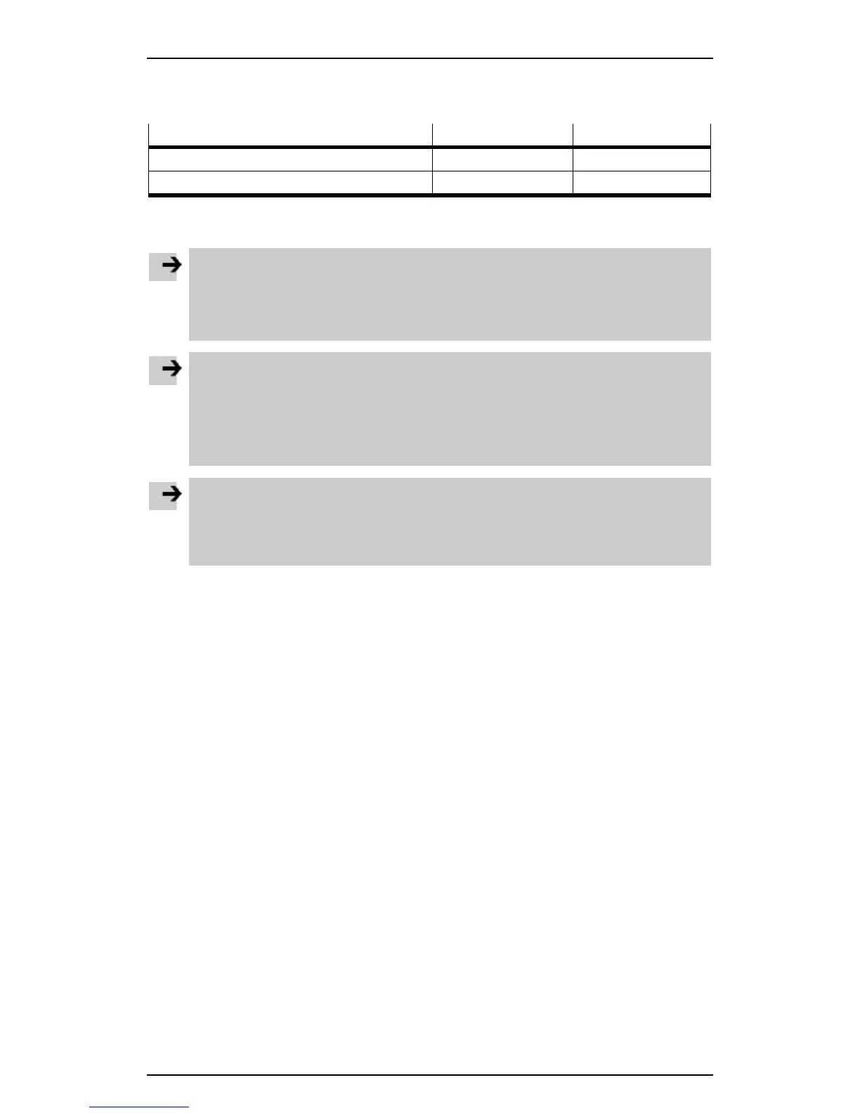
Number of IO-Link connections IO-Link master IO-Link device
CECC-LK 4 1
CECC-S 1 1
One IO-Link device can be connected to each IO-Link master.
The CECC with a higher-order IO-Link master can be connected to the IO-Link device connection.
Note
When connecting two devices (CECC-LK or CECC-S) with a separate power supply via IO-Link,
high equalising currents can occur and damage the devices.
• Connect the earth cables of the devices connected via IO-Link.
This equalises the ground potential.
Note
The maximum residual current for connected IO-Link devices is:
– CECC-LK: max. 10 A for max. 4 IO-Link devices
– CECC-S: max. 3.5 A for max. 1 IO-Link device
The maximum load current at an IO-Link master port (e.g. actuators) is 3.5 A.
• Use external fuse protection if necessary.
Note
A digital standard sensor/actuator can also be connected at each IO-Link master instead of an IO-
Link device (operating mode SIO).
• Make sure that the power for these sensors/actuators is supplied via L+ in SIO operating
mode.
Additional functions such as advanced diagnostics, parameters, alerts are handled via function blocks
( Festo CECC_IOLink_3 library).
Further information on configuring connected IO-Link devices under CODESYS V3 pbF can be found in
the sections Configuring an IO-Link master and Configuring an IO-Link device.