4. Commissioning
4-17
Festo P.BE-MPA-EN en 1108e
Further instructions on commissioning and diagnosing the
MPA pneumatic modules can be found in the MPA-...
electronics description.
MPA-S valve terminal with multipin connection or
AS-Interface
The LEDs on the valves show the switching status of the valve
solenoid coils.
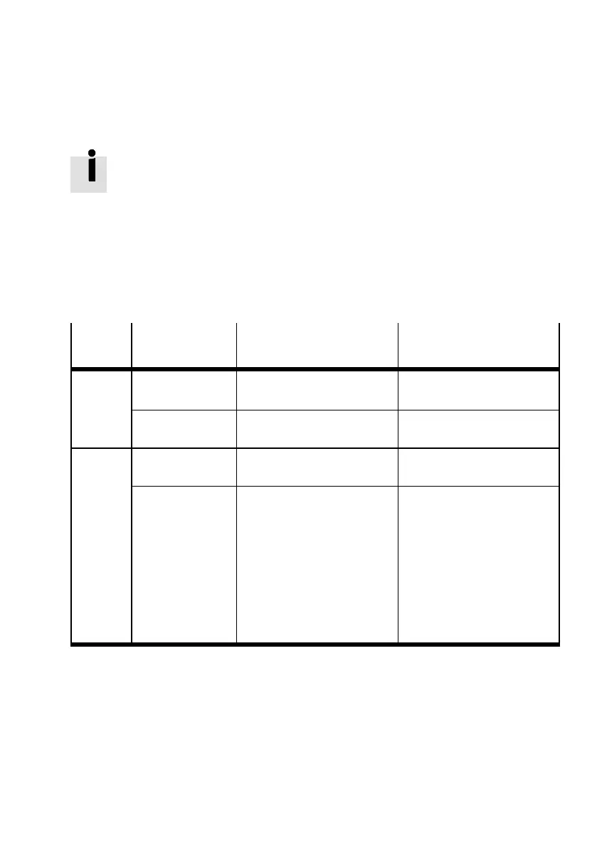
LED
Position of the
valve
Correct state Error status
Out – Normal position logical 0 (signal not present)
–Switching
position
Logical 0 after MO actuated
Lights up
yellow
–Switching
position
logical 1 (signal present)
– Normal position Logical 1 but:
– load voltage of the valves
lies below the permitted
toleranc e range
(18 V ... 30 V)
– Compressed air supply not
OK
or
– Pilot exhaust air blocked
or
– Servicing required
Tab. 4/7: Meaning of the LED display (MPA-S valve terminal with multipin connection or
AS-Interface)