3. Installation
3-11
Festo P.BE-MPA-EN en 1108e
By fitting an additional pneumatic air supply plate within a
pressure zone you can feed additional supply air or extract
exhaust air.
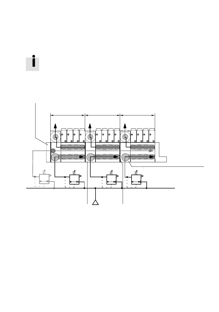
The following diagram shows as an example the assignment
of the supply and exhaust connections to the valves on an
MPA-S valve terminal with blocked channels (1), (3) and (5).
1
234
5
67
(12/14)
(1)
(1) (1)
(3/5) (3/5)
(3/5)
1 Pneumatic interface or multiple
connector plate with supply port (1)
for pressure zone 1 and pilot
connection (12/14) for the complete
valve terminal
2 Pressure zone 1
3 Pressure zone 2
4 Pressure zone 3
5 Air supply plate for pressure zone 3
6 Identification of the pressure zone
separating seal (projecting flag)
7 Air supply plate for pressure zone 2
Fig. 3/6: Example of MPA-S valve terminal with 3 pressure zones