Specifications Product Description
MS-9600 PN 51335:E 7/9/03 15
EIA-485 (ACS) - TB6
ACS annunciator connector, Terminal 1 (+) and Terminal 2 (-)
EIA-485 (TERM) - TB7
Terminal Mode annunciator connector, Terminal 5 (In +), 6 (In -), 7 (Out +), 8 (Out -)
EIA-232 (ACS) - TB7
PC/Printer Connector, Terminal 1 (Transmit), 2 (Receive), 3 (DTR), 4 (Ground)
Auxiliary Trouble Inputs - J16 & J17
Two-pin connectors which can be used to monitor trouble conditions on auxiliary
equipment. They can be connected to the trouble bus of a peripheral such as the
CHG-120F or to the normally-open dry contacts of a trouble relay.
CAUTION! Do not connect power to these connectors since circuit damage may result.
1.3.1 Current Availability
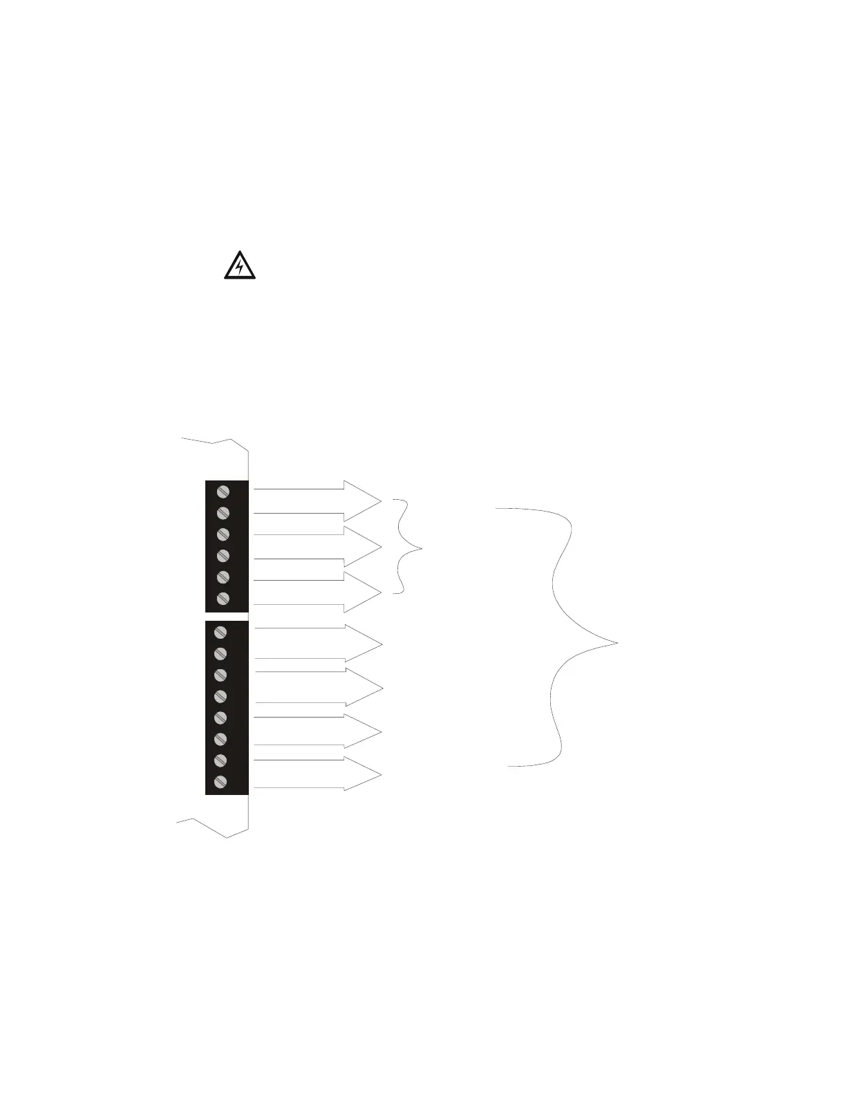
The following figure illustrates the maximum current that is possible for each panel
circuit and the total current available from the FACP power supply.
3 amps max
per circuit
3 amps max
per circuit
3 amps max
per circuit
3 amps max
per circuit
3 amps max
per circuit
3 amps max
per circuit
3 amps max
per circuit
Resettable Power
for 4-Wire
Smoke Detectors
Nonresettable
Power # 1
Nonresettable
Power # 2
NAC # 1
Style Y or Z
NAC # 2
Style Y or Z
NAC # 3
Style Y only
NAC # 4
Style Y only
Standby
6 amps max
per panel
Alarm
7 amps max
per panel
1
2
3
4
5
6
7
8
1
2
3
4
5
6
TB4
TB3
Figure 1.1 Current Availability
powerdist.cdr
Refer to the battery calculations section for additional information.