Installation Mounting
24 MS-9600 PN 51335:E 7/9/03
SECTION 2 Installation
The cabinet may be either semi-flush or surface mounted. The cabinet mounts using
two key slots and two 0.250” (6.35 mm) diameter holes located in the backbox. The
key slots are located at the top of the backbox and the two securing holes at the bottom.
Carefully unpack the system and check for shipping damage. Mount the cabinet in a
clean, dry, vibration-free area where extreme temperatures are not encountered. The
area should be readily accessible with sufficient room to easily install and maintain the
panel. Locate the top of the cabinet approximately 5 feet (1.5 m) above the floor with
the hinge mounting on the left. Determine the number of conductors required for the
devices to be installed. Sufficient knockouts are provided for wiring convenience.
Select the appropriate knockout(s) and pull the conductors into the box. All wiring
should be in accordance with the National and/or Local codes for fire alarm systems.
2.1 Mounting
The circuit board contains static-sensitive components. Always ground yourself with a
proper wrist strap before handling any boards so that static charges are removed from
the body. Use static suppressive packaging to protect electronic assemblies.
Mark and predrill holes in the wall for the top two keyhole mounting bolts
using the dimensions illustrated in Figure 2.2 on page 25
Install two upper fasteners in the wall with the screw heads protruding
Using upper ‘keyholes,’ place backbox over the two screws, level and secure
Mark and drill the lower two holes
Install remaining fasteners and tighten
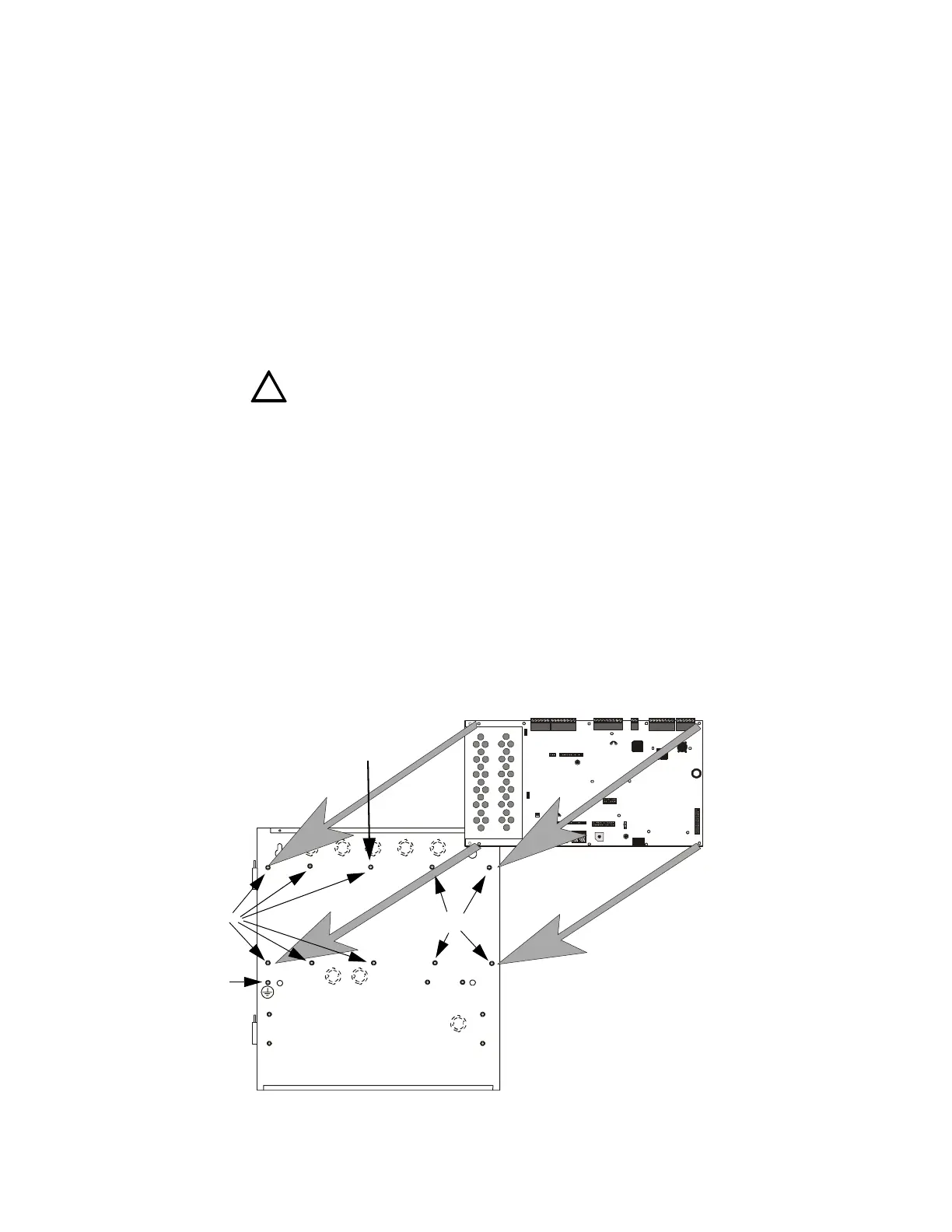
Screw supplied standoffs onto mounting studs in locations indicated below
Attach solid earth ground wire to grounding stud as indicated in Figure 2.1
When the location is dry and free of construction dust, install the main circuit
board by aligning the 10 mounting holes in the circuit board with the 10
mounting standoffs in the backbox as illustrated below
Secure the circuit board to the standoffs with the supplied screws and male/
female standoff as indicated in following figure
!
See Page
+BATTERY-
LCD DI SPLAY
KEYPAD I/F
OPT DACT
HOT
CB1
J3
J2
TB1 TB2
TB3
JP3
JP2
SW1
JP5
JP6
J17
J16
J6
J8
J7
JP10
JP11
REMOVE
TODISABLE
LOCAL
CHARGER
DISABL E
GND
FLT
CUT T O
MO NI TO R 4 XTM
OPT SLC
4XTM O PT BD
TB4
TB5
TB6 TB7 TB8
NEU T E A RTH
Figure 2.1 MS-9600 Main Circuit Board Installation
MS-9600 Backbox
MS-9600 Main Circuit Board
mounting studs
mounting studs
96brdmnt.cdr
IMPORTANT!
Secure circuit board to this standoff with
supplied male/female standoff
grounding stud:
attach solid earth
ground wire (refer to
"AC Power and Earth
Ground Connection"
on page 27)