Notification Appliance Circuits Installation
MS-9600 PN 51335:E 7/9/03 29
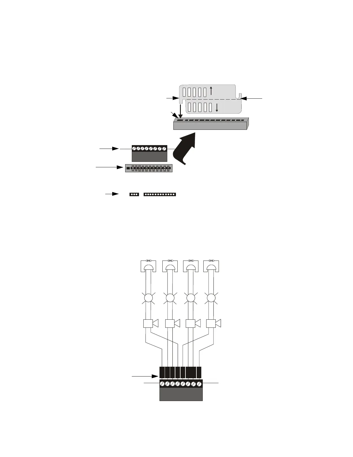
2.4.1 Configuring NACs
The Notification Appliance Circuits on the main circuit board are configured for Style
Y or Style Z by properly orienting the NACKEY card in JP8 which is located at the top
of the main circuit board near the NAC Terminal TB4. The default configuration is for
Style Y (Class B). Refer to Figure 2.6 for information on installing the NACKEY card.
2.4.2 Style Y (Class B) NAC Wiring
J10
J11
4XTMF OPT BD
JP8
Connectors for 4XTMF option module
CLASS A
CLASS B
NACKEY -PCA
NACKEY -PCA
Figure 2.6 NAC Configuration Using NACKEY
NACKEY Card
JP8
Top edge of MS-9600
Main Circuit Board
• Style Z (Class A) - install NACKEY into JP8 with
Class A pointing down toward circuit board as
illustrated to the right.
• Style Y (Class B) - install NACKEY into JP8 with
Class B pointing down toward circuit board .
NACKEY must be inserted with text side facing in
toward center of main circuit board and key into key-
slot as illustrated to the right. It is keyed to prevent
incorrect insertion.
TB4
If the 4XTMF Option Module is to be installed in connectors
J10 and J11, the NACKEY card must be carefully separated
at the scored mark and only the required half installed into
JP8. This will allow room for the 4XTMF module.
scored mark
4XTMF Module connectors
NACKEY card slot
Key
Key-slot
B
+
B
+
B
-
B
-
1
1
-
++++
++++
++++
B
+
B
-
B
+
B
-
33
2
2
44
Figure 2.7 NAC Style Y (Class B) Wiring
4 Style Y (Class B) Notification Appliance Circuits, supervised and power-limited - 4.7 kohm, ½ watt P/N:71252 UL listed
Polarized Bells
Polarized Bells
Polarized Horns
Polarized Horns
Polarized Strobes
Notification Appliance Circuit
polarity shown in alarm state
Dummy Load all unused circuit
TB4
9600nacy.cdr
Polarized Strobes
circuit number
NAC 1
NAC 3
NAC 4
NAC 2