Optional Modules and Devices Installation
MS-9600 PN 51335:E 7/9/03 37
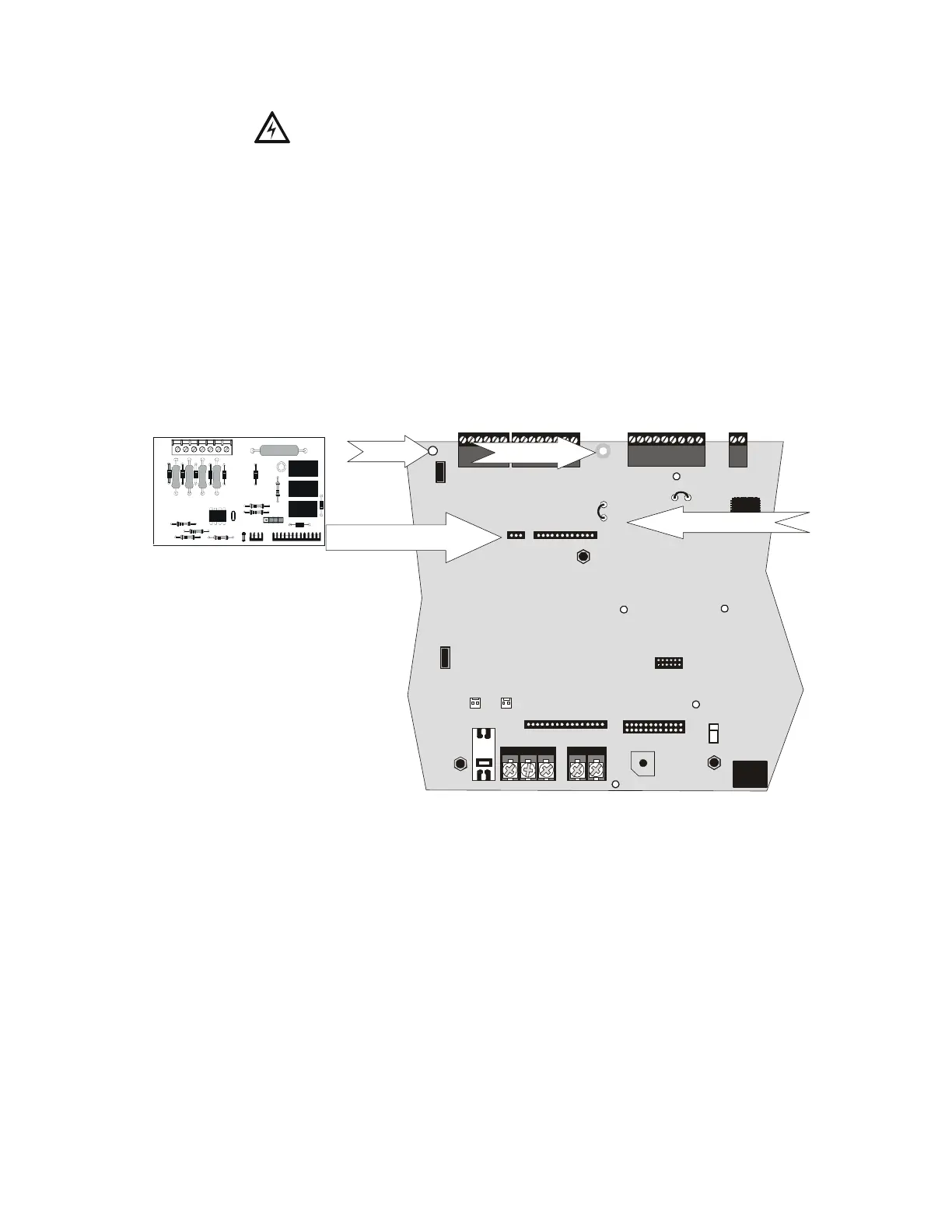
The following steps must be followed when installing the 4XTMF module:
1. Remove all power (AC and DC) from the FACP before installing 4XTMF
2. Cut jumper JP6 on the main circuit board to allow the control panel to supervise
the 4XTMF module
3. Carefully plug the connectors on the 4XTMF module into connectors J10 and J11
on the MS-9600 main circuit board, being careful not to bend any pins
4. Secure 4XTMF module to standoffs with supplied screws.
5. Reapply power to the FACP
6. For proper 4XTMF operation, the output relays must be programmed for the
factory default settings as shown on the PC board silkscreen: Alarm Relay,
Trouble Relay and Supervisory Relay
7. When the installation has been complete, enable the 4XTMF module by sliding
the disconnect switch to the left
8. Test system for proper operation
NOTE: Jumper JP5 on the MS-9600 main circuit board can be used to configure the FACP
supervisory relay for operation with the 4XTMF module. The supervisory relay must be
programmed as shown on the main circuit board silkscreen (TB5, Terminals 7, 8 & 9).
Cutting JP5 will allow the 4XTMF to generate a trouble if the supervisory contact opens
Leaving JP5 in will prevent generation of a trouble if the supervisory contact opens
2.6.3 Auxiliary Trouble Input (J16 & J17)
Auxiliary Trouble Inputs 1 (J17) and 2 (J16), which are located on the MS-9600 main
circuit board, can be used to monitor for trouble conditions on auxiliary equipment such
as power supplies. J16 and/or J17 can be connected to any open collector trouble
output on the auxiliary equipment. The MS-9600 control panel will indicate a trouble
condition if a trouble is sensed at the Auxiliary Trouble Inputs.
If the 4XTMF Module is installed and jumper JP6 on the MS-9600 has been cut to
supervise it, Auxiliary Trouble Input 1 (J17) will monitor the 4XTMF for trouble
conditions.
+BATTERY-
LCD DISPLAY
KEYPAD I/F
OPT DACT
HOT
CB1
J2
TB1
TB2
JP3
TB3
SW1
JP5
JP6
J17
J16
J6
J8
J7
J10
J11
CU T TO
MONITOR 4XTM
4XTM OPT BD
TB4 TB5
TB6 TB7
NEUT EARTH
Figure 2.16 4XTMF Connectors to MS-9600 Connectors
J10 & J11 Connectors
Cut Jumper JP6
Standoff
Standoff
4XTMF
MS-9600
9604xtm1.cdr