Installation Optional Modules and Devices
40 MS-9600 PN 51335:E 7/9/03
2.6.6 Digital Communicator and Annunciators
2.6.6.1 UDACT-F Digital Alarm Communicator/Transmitter
The UDACT-F transmits system status to UL listed Central Station receivers via the
public switched telephone network. It is capable of reporting up to 99 software
zones or up to 636 addressable points. The UDACT-F can be mounted remotely in
a UBS-1F or ABS-8RF enclosure or in the panel cabinet using the P/N: BRKT-9600
Universal Bracket. For additional information, refer to the UDACT-F Manual.
Programming
The MS-9600 must be programmed to operate with the UDACT-F. Refer to
"Annunciators/UDACT" on page 97 for control panel programming information.
2.6.6.2 ACM-8RF Relay Control Module
The ACM-8RF module provides eight Form-C relays with contacts rated for 5
amps. When installed with an MS-9600 FACP, the ACM-8RF modules provide
relay activation for each of the 99 possible FACP zones plus special functions.
Options exist to allow for alarm only or alarm and trouble activation per zone.
Output activation for general alarm, general trouble, general supervisory, NAC
fault, AC fail, walktest start and battery trouble are also available. The ACM-8RF
can be mounted remotely in an ABS-8RF annunciator surface-mount backbox or in
the panel cabinet using the P/N: BRKT-9600 Universal Bracket. Refer to the
ACM-8RF manual for information on setting module switches for addressing and
relay functions.
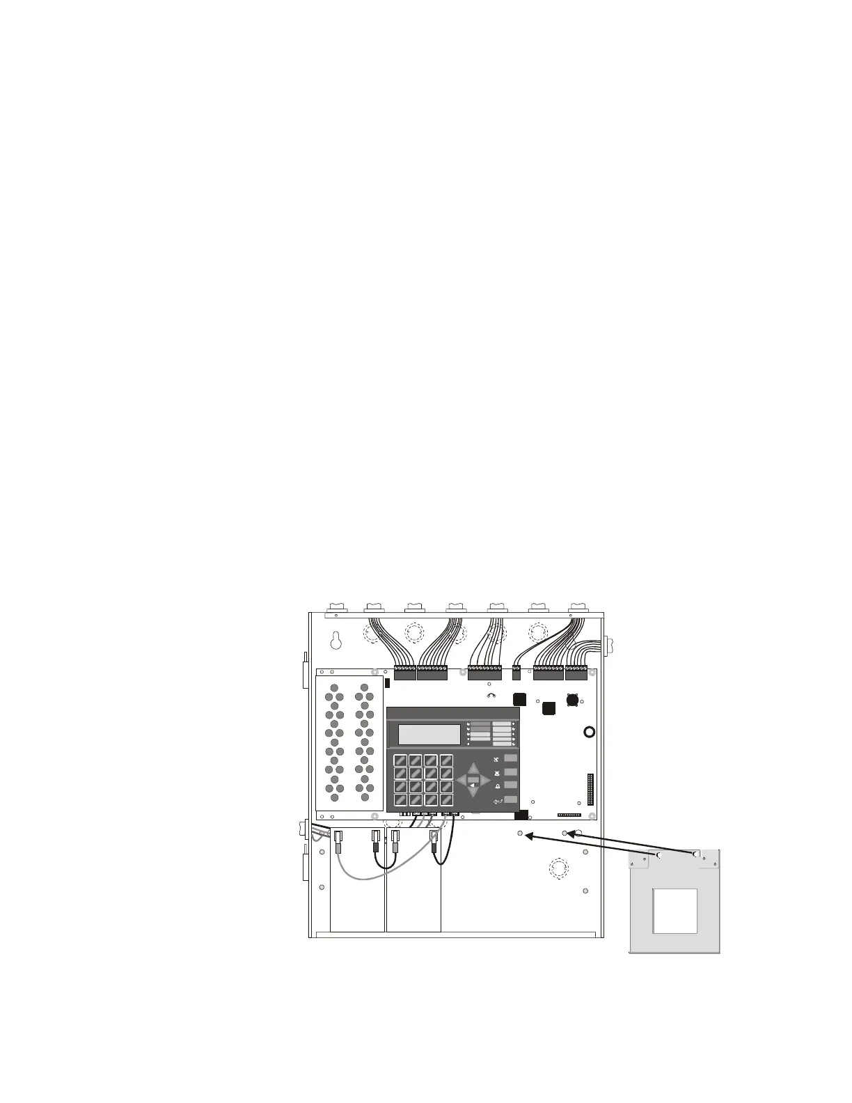
2.6.6.3 BRKT-9600 Universal Bracket Installation
The optional BRKT-9600 Universal Bracket can be used to mount specific modules
inside the MS-9600 cabinet. The BRKT-9600 mounts to two studs located in the
lower right corner of the control panel cabinet as illustrated below. It is secured to
the PEM studs on the back wall of the cabinet with two supplied hex nuts.
IMPORTANT! When the BRKT-9600 is installed, the MS-9600 cabinet can hold a
maximum of two 12 Amp Hour batteries with the orientation illustrated below.
Reference
Manual
See Page
Reference
Manual
+BAT TERY-
LCD DISPLAY
KEYPAD I/F
1
2
3
OPT DA CT
HOT
CB1
J3
J12
J2
TB1
TB2
TB3
JP3
JP2
JP8
JP4
JP7
JP5
JP6
J17
J16
J6
J8
J7
JP10
JP11
REMOVE
TO DISABLE
LOCAL
CHARGER
DISA BLE
GND
FLT
CUT T O
MONITOR 4XTM
OPT SLC
4XTM OPT BD
TB4
TB5
TB6 TB7 TB8
NEUT E ARTH
1
4
*
2
5
0
3
6
#
1
st
EVEN T
ABC
DEF
GHI
JKL MNO
PRS
TUV WXY
QZ
-/.
CLR
78 9
ESC
ENTER
RECALL
ACK/STEP
ALARM
SILENCE
DRILL
HOLD 2 SEC
RESET
MODE
MAINTENANCE
GROUND
BATTERY
DISABLED
ALARM
SILEN CED
TROUBL E
SUPERVISORY
FIRE ALARM
AC POWER
Figure 2.19 BRKT-9600 Bracket Installation
Mount BRKT-9600 to PEM
studs on back of cabinet
using supplied hex nuts.
MS-9600 Cabinet
96brkmnt.cdr