Assembly
5.1 Preparatory work
28 Edition 09/2022 M3560-02en
When arranging the threaded hole, note the difference between the A or B variant of the
coupling part 1 (1) or 2 (2).
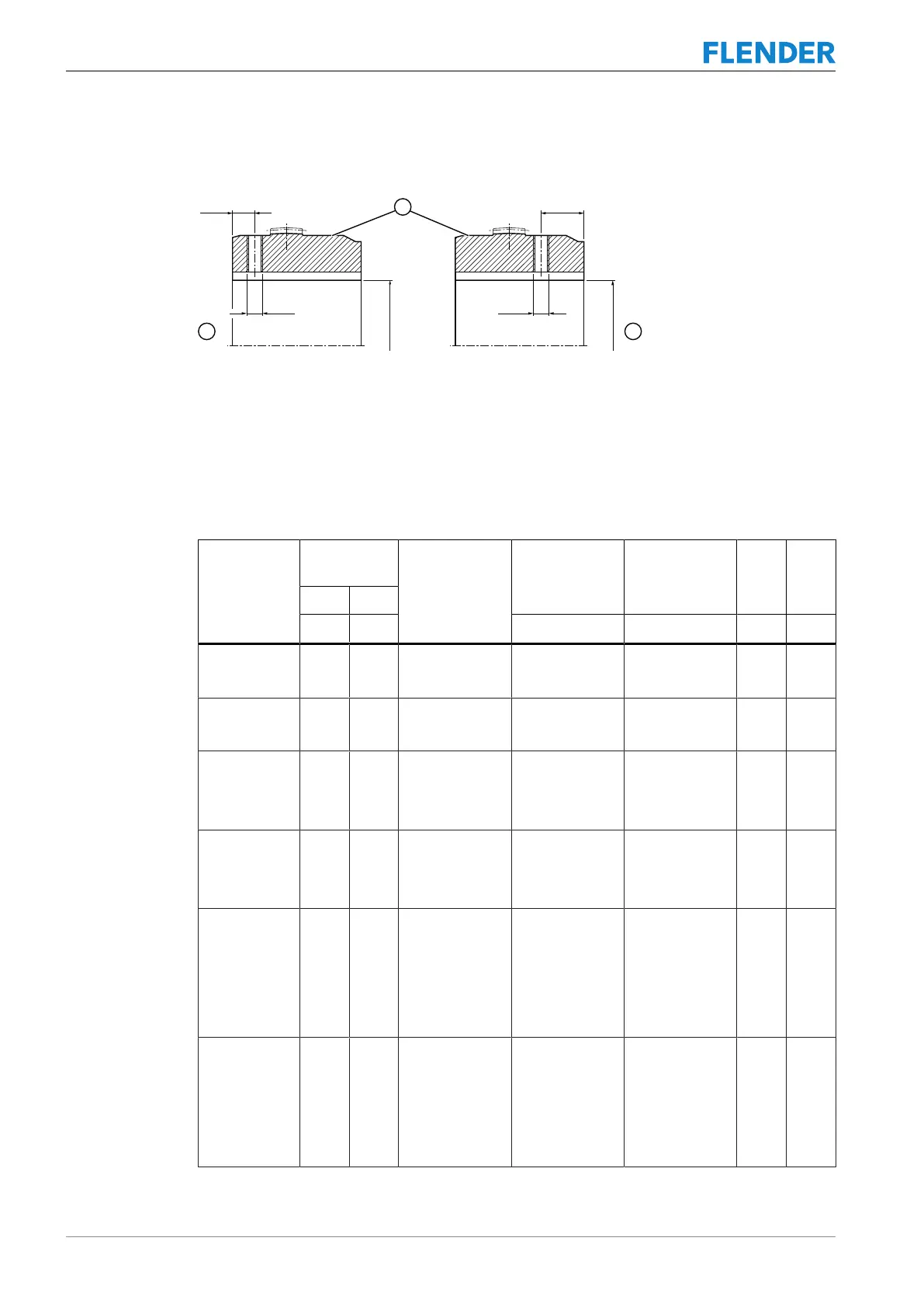
Figure5-2:Diameter and axial position of the threaded hole in the hub
① Sealing surface
② Coupling part 1 or 2, A variant
③ Coupling part 1 or 2, B variant
The following table contains the values for the diameter of the threaded hole depending on
the coupling size and the finished bore D and the axial position of the threaded hole on the
hub.
Coupling size Finished
bore D
Threaded hole
d1
Tightening
torque TA
Width A/F in-
ternal hexagon
e1 e2
Over Up to
mm mm Nm mm mm mm
83 10
17
17
50
M5
M6
3
4
2.5
3
7 16
107 10
17
17
65
M5
M6
3
4
2.5
3
10 16
130 10
17
38
17
38
82
M5
M6
M8
3
4
8
2.5
3
4
10 24
156 10
17
22
17
22
100
M5
M6
M8
3
4
8
2.5
3
4
15 27
181 10
17
22
30
65
17
22
30
65
116
M5
M6
M8
M10
M12
3
4
8
15
25
2.5
3
4
5
6
16 30
211 10
17
22
30
38
17
22
30
38
137
M5
M6
M8
M10
M12
3
4
8
15
25
2.5
3
4
5
6
18 35