Assembly
5.3 Aligning the coupling
34 Edition 09/2022 M3560-02en
The recommended alignment values are specified as numerical values in Distances between
teeth VA and recommended alignment values for angular and radial misalignment
(Page67) . Do not align the coupling more accurately than this, as the lubrication film form-
ation will then be compromised.
5.3.2 Possible misalignment5.3 Aligning the coupling
The following types of misalignment can occur:
ǡ,B4
NBY
4
NJO
ǡ,B
4
NBY
ǡ,X
ǡ44
NBY
4
NJO
4
NJO
ǡ,S
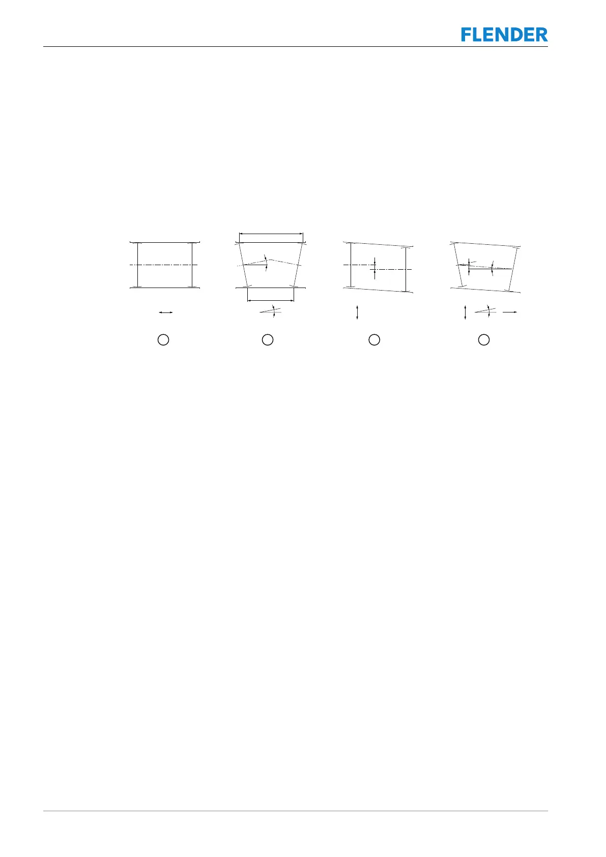
Figure5-4:Possible misalignment
① Axial misalignment (ΔKa)
② Angular misalignment (ΔKw)
③ Radial misalignment (ΔKr)
④ Axial, angular and radial misalignment
5.3.2.1 Axial misalignment5.3 Aligning the coupling
Set the axial misalignment ΔKa to a value within the permissible tolerance range for the S
clearance.
The values for the S clearance are to be considered as the maximum permissible increase in
the hub distance of the coupling.
You can find the values for clearance S under Clearance S (Page66).
5.3.2.2 Angular misalignment5.3 Aligning the coupling
The ZNN, ZNNV, ZNZS and ZNZV types compensate for positional deviations of the shaft
ends to be connected up to a maximum angular misalignment of ΔKw=0.5°.
The ZNNA and ZNZA types compensate for positional deviations of the shaft ends to be con-
nected up to a maximum angular misalignment of ΔKw=0.2°.
Determine the value ΔS (ΔS = S
max
- S
min
).
ZNN, ZNNV, ZNZS, ZNZV types:
ΔS = S
max
- S
min
≤ ND x tan 0.5° ≈ ND / 100
ZNNA, ZNZA types:
ΔS = S
max
- S
min
≤ ND x tan 0.2° ≈ ND / 300