Assembly
5.1 Preparatory work
M3560-02en Edition 09/2022 29
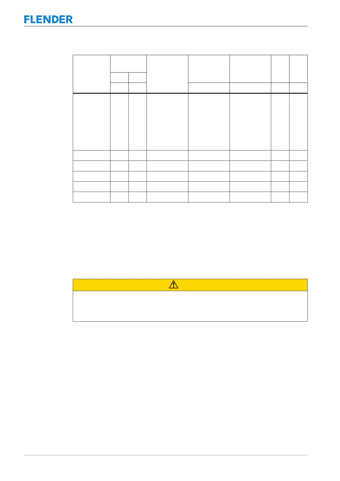
Coupling size Finished
bore D
Threaded hole
d1
Tightening
torque TA
Width A/F in-
ternal hexagon
e1 e2
Over Up to
mm mm Nm mm mm mm
250 10
17
22
30
38
50
17
22
30
38
50
164
M5
M6
M8
M10
M12
M16
3
4
8
15
25
70
2.5
3
4
5
6
8
22 40
274 80 178 M16 70 8 25 46
307 90 198 M16 70 8 30 54
333 100 216 M16 70 8 30 61
364 120 242 M20 130 10 30 50
424 150 288 M24 230 12 30 50
Table5-2: Diameter and axial position of the threaded hole, tightening torque and width A/F
Apply the specified tightening torques as listed in Section Tightening procedure (Page69).
Position of the threaded hole with respect to the parallel keyway
Position the threaded hole for the set screw on the parallel keyway.
Selection of the set screw
CAUTION
Physical injury
Risk of injury from protruding set screw.
• Please observe the information about selecting the set screw.
Use set screws in accordance with ISO 4029 with a toothed cup point. The size of the set
screw is determined by the bore made. The set screw should fill out the threaded hole as
much as possible and must not protrude beyond the hub.