FLUXUS WD100, WD200 6 Installation of the Transmitter
32 UMFLUXUS_F5WDV1-1EN, 2016-04-08
6.5 Connection of the Outputs
• Remove the second blind plug from the right for the connection of the outputs (see Fig. 6.10).
• Prepare the output cable with an M20 cable gland.
• Push the extension cable through the cap nut, the compression part and the basic part of the cable gland (see Fig. 6.11).
• Insert the output cable into the housing.
• Screw the gasket ring side of the basic part tightly into the housing.
• Fix the cable gland by screwing the cap nut onto the basic part (see Fig. 6.11).
• Connect the leads to the terminals of the transmitter (see Fig. 6.10 and Fig. 6.6).
• Close the transmitter. Screw the front plate onto the housing.
These settings can be changed. For the installation of the outputs see section 15.1. For the activation of the outputs see
section 15.3...15.5.
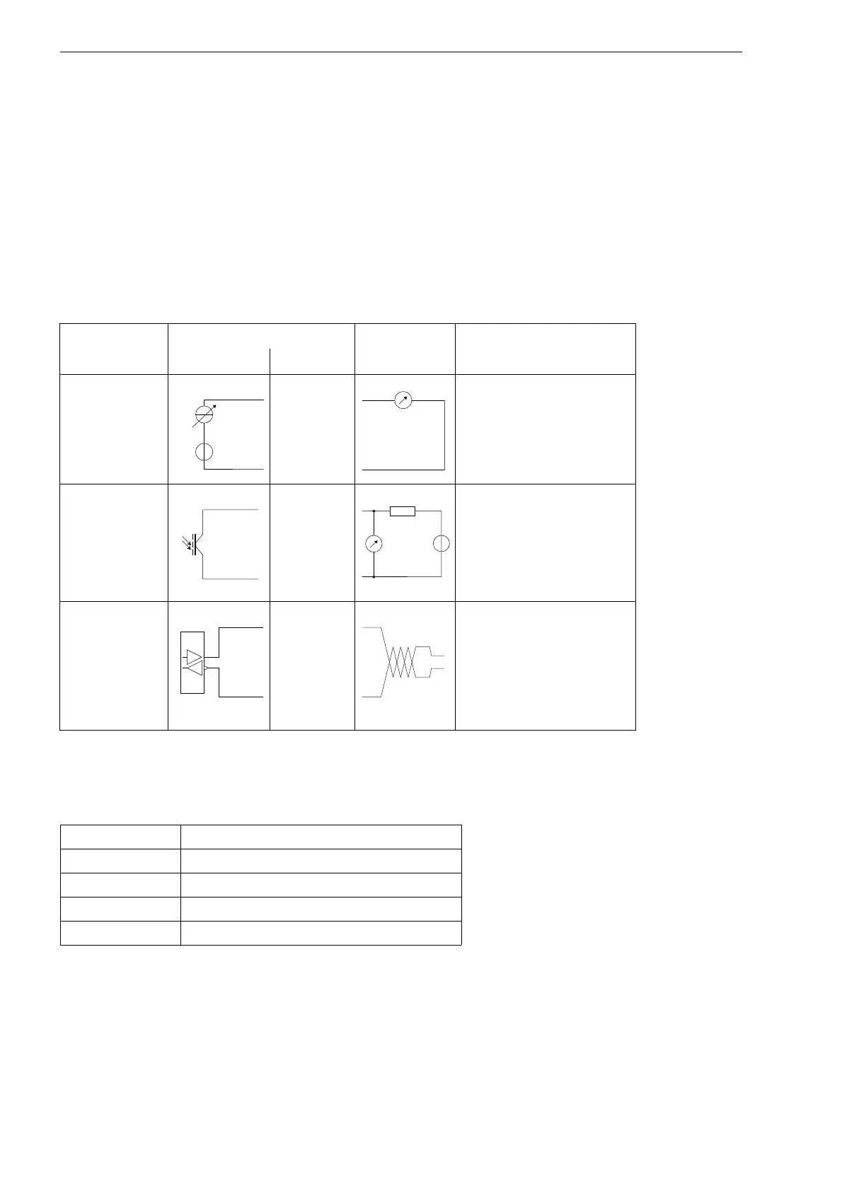
Tab. 6.1: Circuits of the outputs
output transmitter external circuit remark
internal circuit connection
active current
loop I1: 6
I1: 5
R
ext
< 500 Ω
binary output
(optorelay) B1/B2: 2/4
B1/B2: 1/3
U
ext
= 28 V DC
I
c
≤ 100 mA
RS485
8 (A+)
7 (B-)
120 Ω
termination resistor
shield 9
The number, type and connections of the outputs are customized.
R
ext
is the sum of all ohmic resistances in the circuit (e.g. resistance of the conductors, resistance of the am-
peremeter/voltmeter).
Tab. 6.1: Factory presets of the outputs
output current output I1
source item measured value
measured value current physical quantity
output range 4...20 mA
error value 3.5 mA