6 Installation of the Transmitter FLUXUS WD100, WD200
UMFLUXUS_F5WDV1-1EN, 2016-04-08 25
6.3 Connection of the Transducers
It is recommended to run the cables from the measuring point to the transmitter before connecting the transducers to
avoid load on the connectors.
6.3.1 Connection of the Transducers to the Transmitter
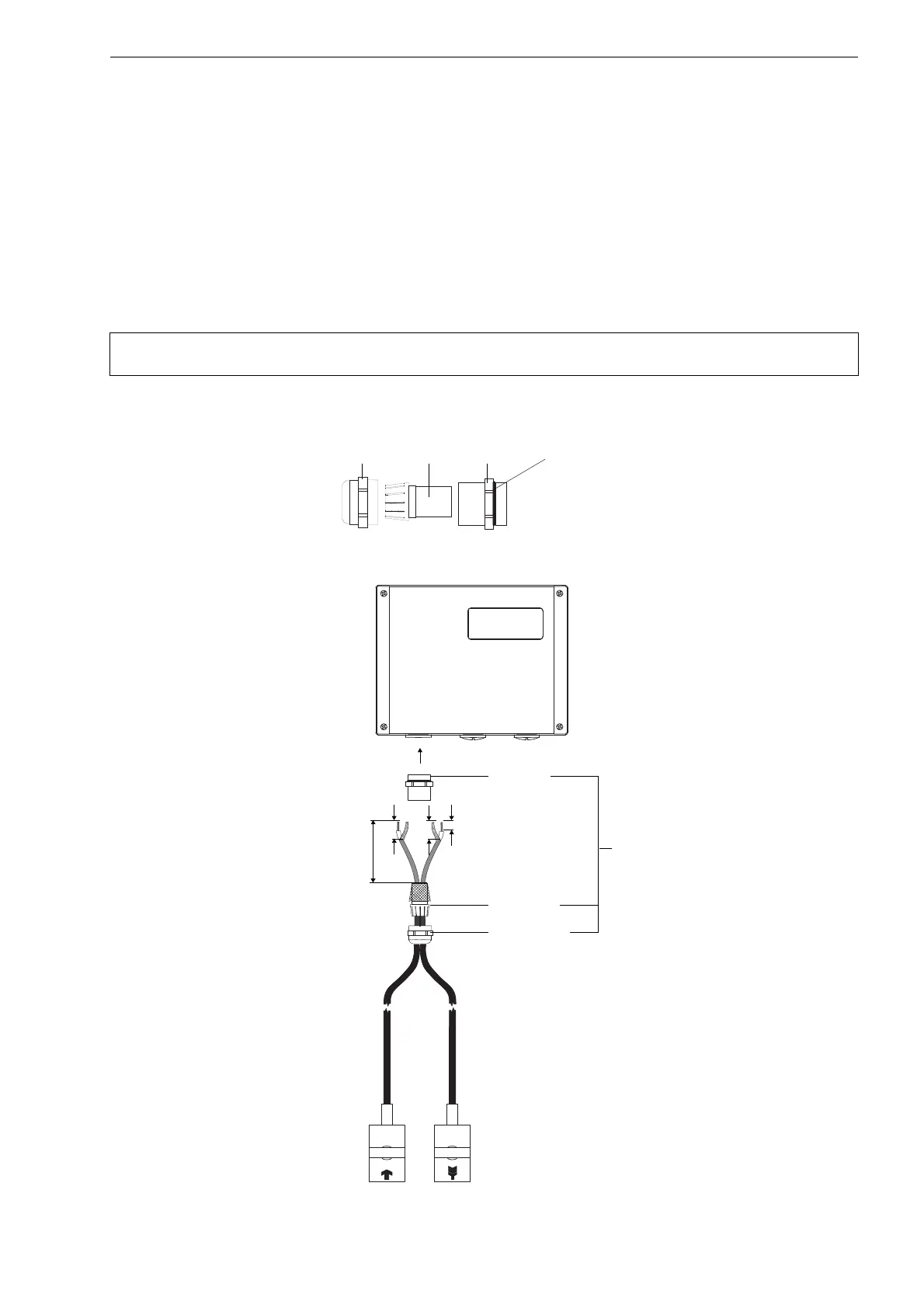
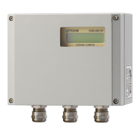
• Remove the left blind plug for the connection of the transducer cable (see Fig. 6.5).
• Open the cable gland of the transducer cable (see Fig. 6.4)
• Push the transducer cable through the cap nut and the compression part.
• Screw the gasket ring side of the basic part tightly into the housing.
• Insert the transducer cable into the housing.
• Fix the cable gland by screwing the cap nut onto the basic part.
• Connect the leads to the terminals of the transmitter (see Fig. 6.6 and Tab. 6.1).
Attention! For good high frequency shielding, it is important to ensure good electrical contact between the exter-
nal shield and the cap nut (and the housing).
Fig. 6.4: Cable gland
Fig. 6.5: Transducers – direct connection
cap nut compression part basic part gasket ring side
of the basic part
basic part
cable gland
7 mm
compression
part
cap nut
20 mm
45 mm
25 mm



 To Next Page