6 Installation of the Transmitter FLUXUS WD100, WD200
UMFLUXUS_F5WDV1-1EN, 2016-04-08 31
6.4 Connection of the Power Supply
• Remove the right blind plug for the connection of the power supply (see Fig. 6.10).
• Prepare the power cable with an M20 cable gland.
• Push the extension cable through the cap nut, the compression part and the basic part of the cable gland (see Fig. 6.11).
• Insert the power cable into the housing (see Fig. 6.10).
• Screw the gasket ring side of the basic part tightly into the housing.
• Fix the cable gland by screwing the cap nut on the basic part (see Fig. 6.11).
• Connect the leads to the terminals of the transmitter (see Fig. 6.10 and Tab. 6.6).
Attention! The degree of protection of the transmitter will only be guaranteed if the power cable fits firmly and
tightly in the cable gland.
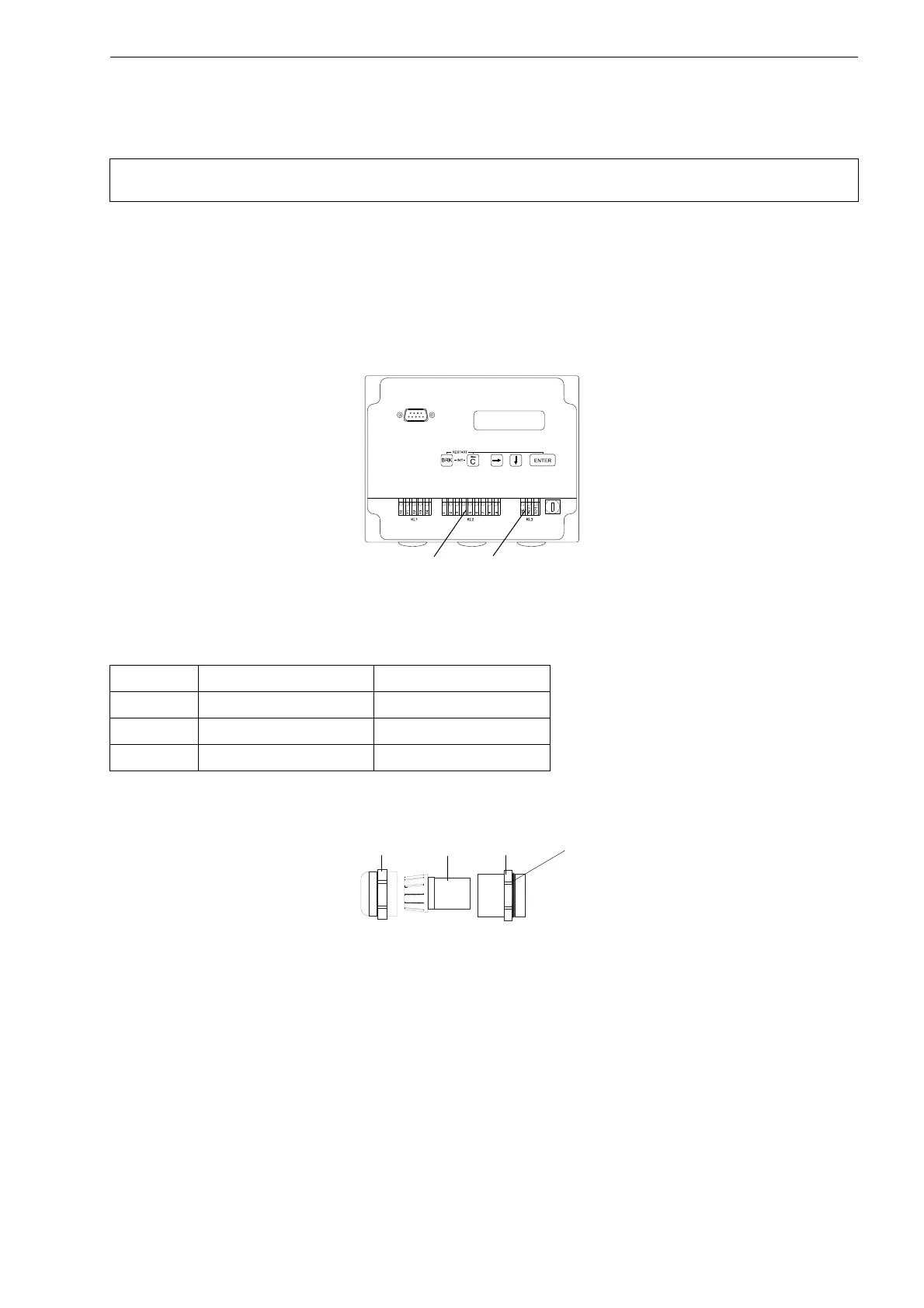
Fig. 6.10: Connection to the transmitter
Tab. 6.6: Terminal assignment - Connection of the power supply
terminal connection AC connection DC
PE earth earth
N(-) neutral - DC
L(+) phase + DC
Fig. 6.11: Cable gland
cap nut
compression
part
basic part
gasket ring side
of the basic part