FLUXUS WD100, WD200 6 Installation of the Transmitter
30 UMFLUXUS_F5WDV1-1EN, 2016-04-08
• Insert the extension cable into the junction box.
• Prepare the extension cable.
• Cut the outer shield and brush it back.
• Pull the extension cable back until the brushed back external shield is below the shield terminal (see Fig. 6.9). The exten-
sion cable must remain completely insulated up to the shield terminal.
• Screw the gasket ring side of the basic part into the junction box.
• Fix the cable gland by screwing the cap nut onto the basic part.
• Fix the extension cable and the external shield to the shield terminal.
• Connect the extension cable to the terminals of the transmitter (see Fig. 6.9 and Tab. 6.3).
6.3.4 Connection of the Transducer Cable to the Junction Box
• Remove the left blind plug for the connection of the transducers (see Fig. 6.5).
• Open the cable gland of the tranducer cable (see Fig. 6.4).
• Push the extension cable through the cap nut and the compression part.
• Cut the external shield and brush it back over the compression part.
• Screw the gasket ring side of the basic part tightly into the housing.
• Insert the transducer cable into the housing.
• Fix the cable gland by screwing the cap nut onto the basic part.
• Connect the leads to the terminals of the junction box (see Fig. 6.8 or Fig. 6.9 and Tab. 6.5).
Attention! The external shield of the extension cable must not have electrical contact to the junction box. There-
fore, the extension cable must remain completely insulated up to the shield terminal.
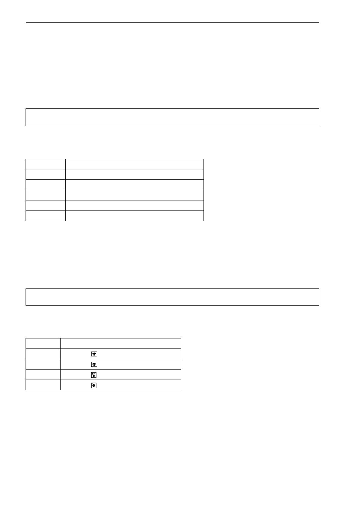
Tab. 6.4: Terminal assignment (extension cable, KL2)
terminal connection
TV white or marked cable (core)
TVS white or marked cable (internal shield)
TRS brown cable (internal shield)
TR brown cable (core)
shield terminal external shield
Attention! For good high frequency shielding, it is important to ensure good electrical contact between the exter-
nal shield and the cap nut (and the housing).
Tab. 6.5: Terminal assignment (transducer cable, KL1)
terminal connection
TV transducer (core)
TVS transducer (inner shield)
TRS transducer (internal shield)
TR transducer (core)