6 Installation of the Transmitter FLUXUS WD100, WD200
UMFLUXUS_F5WDV1-1EN, 2016-04-08 29
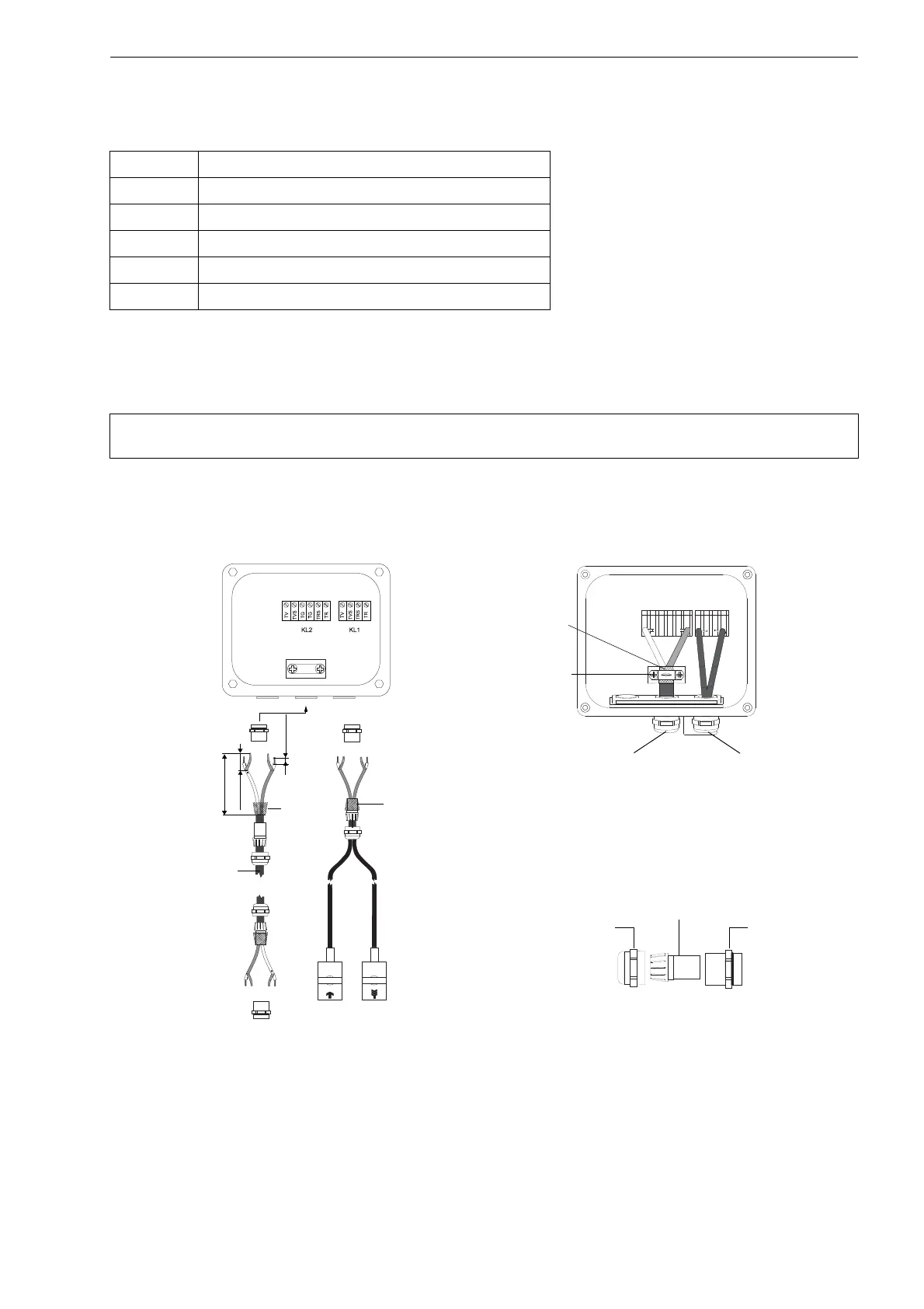
6.3.3.2 With Potential Separation
If earthing on the same potential cannot be ensured e.g., in measurement arrangements with long extension cables, ex-
tension cables and junctions boxes have to be insulated from each other. The junction box and the transducers have to be
on the same potential. Thus, no transient currents can enter the transmitter via the extension cable.
• Remove the blind plug for the connection of the extension cable (see Fig. 6.9).
• Open the cable gland of the extension cable. The compression part remains in the cap nut.
• Push the extension cable through the cap nut, the compression part and the basic part of the cable gland.
Tab. 6.3: Terminal assignment (extension cable, KL2)
terminal connection
TV white or marked cable (core)
TVS white or marked cable (internal shield)
TRS brown cable (internal shield)
TR brown cable (core)
cable gland external shield
Note! For the installation of transducers to pipes with cathodic corrosion protection see document
TIFLUXUS_GalvSep.
Fig. 6.9: Connection of the extension cable and the transducer cable to the junction box JBP3
T V
T V S
T R S
T R
T V
T V S
T G
T G
T R S
T R
100 mm
20 mm
10 mm
external shield,
brushed back
extension cable
shield terminal
extension cable
transducer cable
external
shield
external
shield
cap nut
compression part
basic part
cable gland