9 Basic Measurement FLUXUS WD100, WD200
UMFLUXUS_F5WDV1-1EN, 2016-04-08 47
9.6.1 Fine Adjustment of the Transducer Distance
In case of large deviations, check if the entered parameters are correct or repeat the measurement at a different point on
the pipe.
9.6.2 Consistency Check
If a wide range for the sound speed has been entered in the program branch Parameter or the exact parameters of the
fluid are not known, a consistency check is recommended.
The transducer distance can be displayed during measurement by scrolling with key .
The optimum transducer distance is calculated on the basis of the measured sound speed. It is therefore a better approx-
imation than the first recommended value which had been calculated on the basis of the sound speed range entered in the
program branch Parameter.
If the difference between the optimum and the entered transducer distance is less than specified in Tab. 9.1, the measure-
ment is consistent and the measured values are valid. The measurement can be continued.
If the difference is greater, adjust the transducer distance to the displayed optimum value. Afterwards, check the signal
quality and the signal amplitude bar graph (see section 9.6.1). Press ENTER.
If the displayed transducer distance is adjusted, press ENTER.
The measuring for the positioning of the transducers is started.
The amplitude of the received signal is displayed by the bar graph S=.
• Shift a transducer slightly within the range of the recommended transducer distanceuntil
the bar graph reaches its max. length (max. 6 squares).
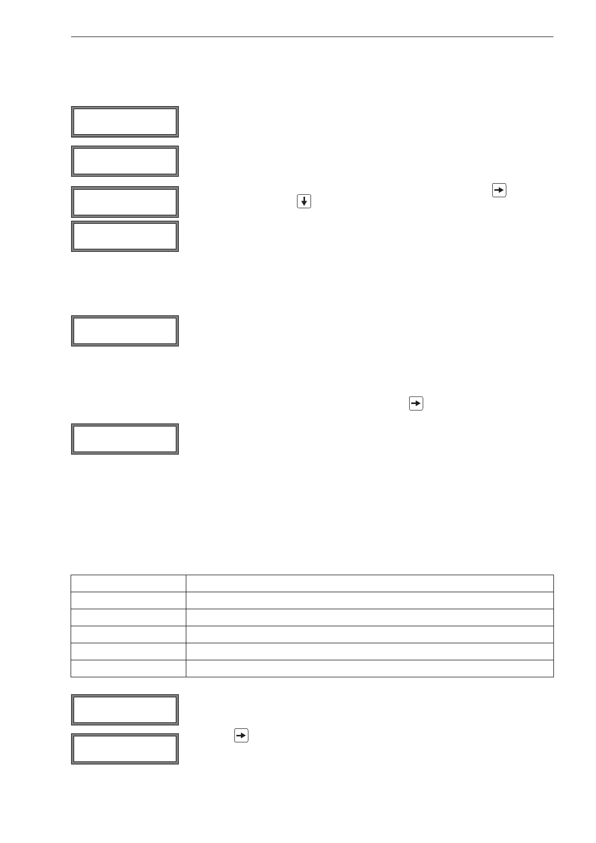
The following quantities can be displayed in the upper line by pressing key and in the
lower line by pressing key :
• ■<>■ =: transducer distance
• time: Transit time of the measuring signal in μs
• S=: signal amplitude
• Q=: signal quality, bar graph has to have max. length
If the signal is not sufficient for measurement, Q= UNDEF will be displayed.
After the precise positioning of the transducers, the recommended transducer distance is
displayed again.
Enter the actual (precise) transducer distance. Press ENTER.
The optimum transducer distance (here: 50.0 mm) is displayed in the upper line in paren-
theses, followed by the entered transducer distance (here: 54.0 mm). The latter value has
to correspond to the adjusted transducer distance. Press ENTER to optimize the transduc-
er distance.
Tab. 9.1: Standard values for signal optimization
transducer frequency difference between the optimum and the entered transducer distance [mm]
G20
K15
M10
P8
Q6
Enter the new adjusted transducer distance. Press ENTER.
Press key again to scroll until the transducer distance is displayed and check the dif-
ference between the optimum and the entered transducer distance. Repeat the steps if
necessary.
time= 94.0 μs
Q=■■■■■■■■■■■
L=(50.0) 54.0 mm
54.5 m3/h
L=(51.1) 50.0 mm
54.5 m3/h