7 Connection PIOX S70x
UMPIOX_S7V4-6-3EN, 2018-10-10 51
PIOX S704
• Insert the transducer cable with the SMB connectors into the housing.
• Fix the transducer cable by tightening the cable gland.
• Connect the SMB connectors to the sockets of the transmitter (see Fig. 7.1, Fig. 7.4 and Tab. 7.1).
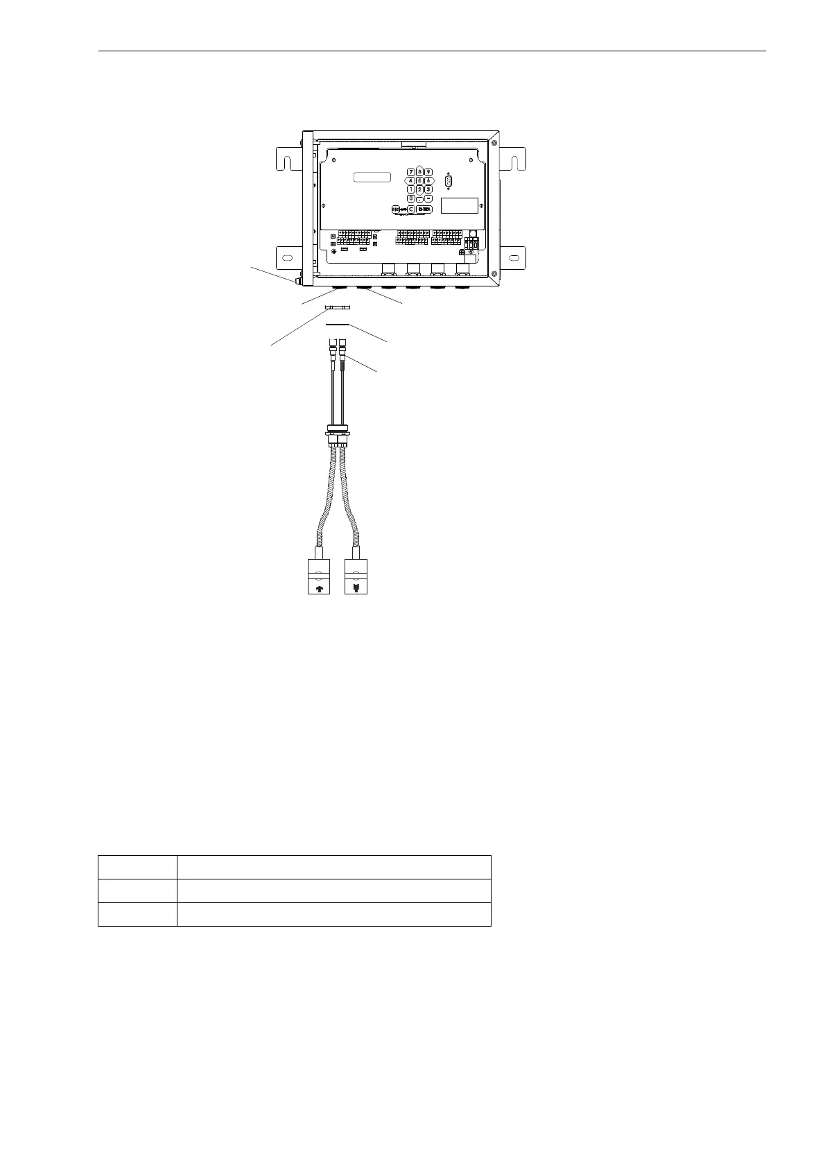
PIOX S705
• Push the transducer cable through the sealing ring (only for cable gland M20, not for cable gland 1/2 NPS).
• Insert the transducer cable with the SMB connectors into the housing.
• Fix the transducer cable by tightening the cable gland with the counter nut.
• Connect the SMB connectors to the sockets of the transmitter (see Fig. 7.2, Fig. 7.5 and Tab. 7.1).
Fig. 7.5: Connection of the transducer cable with SMB connectors
to the transmitter PIOX S705
Tab. 7.1: Terminal assignment (transducer cable)
terminal connection
X_AV SMB connector (brown cable, marked white)
X_AR SMB connector (brown cable, marked black)
AVS
AV
AGN
ARS
AR
BVS
BV
BGN BRS
BR
SA1 SA2 SA3
SA4
SB1
SB2
SB3
SB4
T1a T1b
S2 T2a
T3a
T3b
S4
T4a
T2b
T4b
T1A
T1B
S1 T2A
T3A
T3B
S3
T4A
T2B
T4B
A+
B-
P1+ P2+
P4+
P5a
P6a P7a
P3+
101
103
P1- P2-
P4-
P5b
P6b
P7b
P3-
PE
N(-)
L(+)
SMB connector
transducers
measuring channel B
transducers
measuring channel A
counter nut
sealing ring: only for cable gland M20,
not for cable gland 1/2 NPS
equipotential
bonding
terminal

 Loading...


