PIOX S70x 7 Connection
62 UMPIOX_S7V4-6-3EN, 2018-10-10
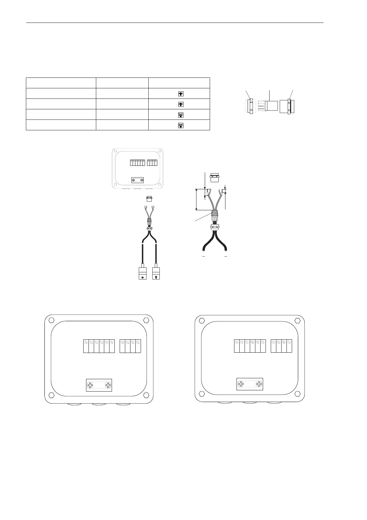
• Fix the cable gland by screwing the cap nut onto the basic part.
• Connect the transducer cable to the terminals of the junction box (see Fig. 7.19 or Fig. 7.20 and Tab. 7.9).
Tab. 7.9: Terminal assignment (KL1)
terminal (JBP2, JBP3) terminal (JB01) connection
TV V transducer (core)
TVS VS transducer (shield)
TRS RS transducer (shield)
TR R transducer (core)
Fig. 7.17: Cable gland
Fig. 7.18: Connection of the transducer cable
with plastic cable jacket and stripped cable ends
Fig. 7.19: Terminal designation (junction box JBP2, JBP3)
Fig. 7.20: Terminal designation (junction box JB01)
cap nut
compression part basic part
T V
T V S
T G
T G
T R S
T R
K L 2 K L 1
T V
T V S
T R S
T R
external shield,
brushed back
T V
T V S
T G
T G
T R S
T R
T V
T V S
T R S
T R
K L 2 K L 1
T V
T V S
T G
T G
T R S
T R
V
V S
R S
R
K L 2 K L 1

 Loading...


