Description of the machine
Fliegl Agrartechnik GmbH, 84453 Mühldorf am Inn, Germany
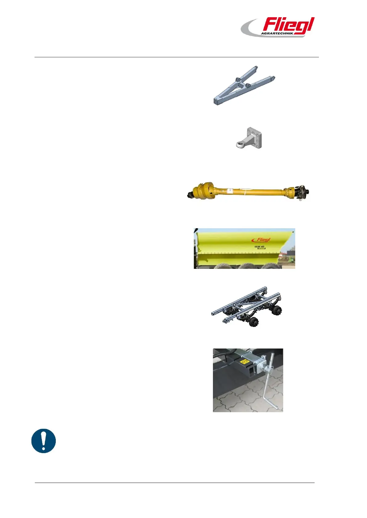
Item 9 – draw gear
An adjustable drawbar for bottom attachment is
fitted by default.
Fig. 15: Assembly – item 9
Item 10 – flange coupling
Flange couplings are available in different
standards and designs.
Fig. 16: Assembly – item 10
Item 11 – through drive
The through drive powers the longitudinal screw
conveyor as well as the main screw conveyor via an
angle gear.
Fig. 17: Assembly – item 11
Item 12 – body
The height and length of the side walls and the
bridge width are type-specific. The bridge is self-
supporting and thus forms the main frame of the
vehicle.
Fig. 18: Assembly – item 12
Item 13 – axle assembly
Different axle assemblies are available for the
ASW.
Single-axle
Tandem
Tridem
Fig. 19: Assembly – item 13
Item 14 – parking brake
The parking brake secures the ULW when parked
so that it cannot roll away.
Spindle brake
Fig. 20: Assembly – item 14
The equipment is part of the DE version and may differ from your version.