GEAR/HYDRAULIC group. The outboard
brakes receive power from the right essential
bus through the OUTBD BRAKES circuit
breaker located on the copilot’s circuit breaker
panel, also in the GEAR/HYDRAULIC group.
Anti-Skid Protection
Anti-skid protection is provided by the BCU
and controls braking on each main gear wheel
independently, thus allowing maximum brak-
ing under all runway conditions without tire
skidding. With anti-skid on, and the brakes ap-
plied, the BCU receives pedal transducer sig-
nals, wheel speed transducer inputs, and
brakeline pressure transducer inputs. If a
wheel begins to skid, the BCU reduces the sig-
nal to the appropriate brake control valve to
arrest the skid.
The anti-skid function is selected via the ANTI-
SKID switch located on the GEAR/HYD con-
trol panel (Figure 14-19). When the anti-skid
system is on, the S/I will be blank, when the
system has been turned off, an OFF legend is
displayed on the S/I, and an amber “ANTI-
SKID FAIL” CAS message is posted. Anti-
skid malfunctions may also result in the
anti-skid CAS message being displayed, which
may indicate a failure of one or more of the anti-
skid circuits or transducers. See Table 14-1
for CAS messages.
The anti-skid switch is normally left on, al-
though the anti-skid function is inoperative at
slow speeds (below 10 knots).
14-19
FOR TRAINING PURPOSES ONLY
LEARJET 45 PILOT TRAINING MANUAL
FlightSafety
international
LEARJET 45 PILOT TRAINING MANUAL
FlightSafety
international
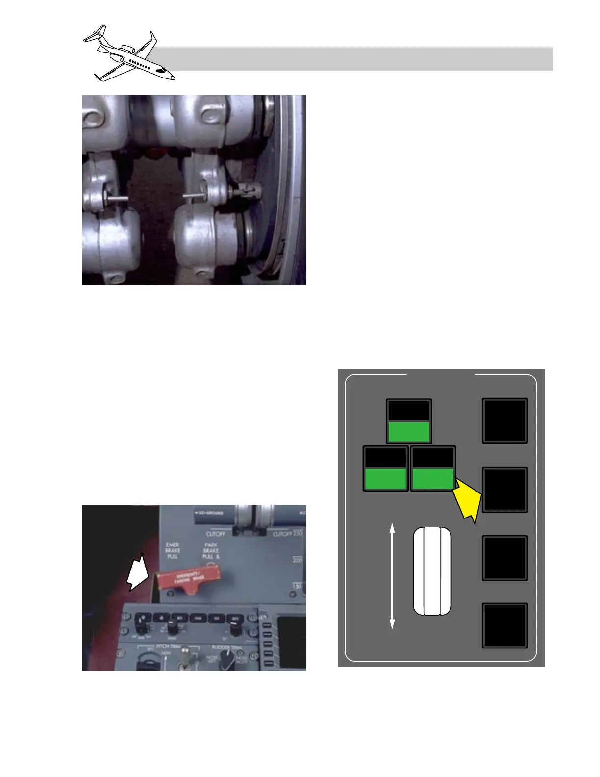
Figure 14-18. Emergency/Parking Brake
Figure 14-17. Brake Assembly