Brake System Indications
Brake accumulator hydraulic pressure is nor-
mally displayed on the EICAS SUMRY page
(Figure 14-20). It can also be displayed on
the EICAS/MFD hydraulic system schematic
display (Figure 14-22). Operating under de-
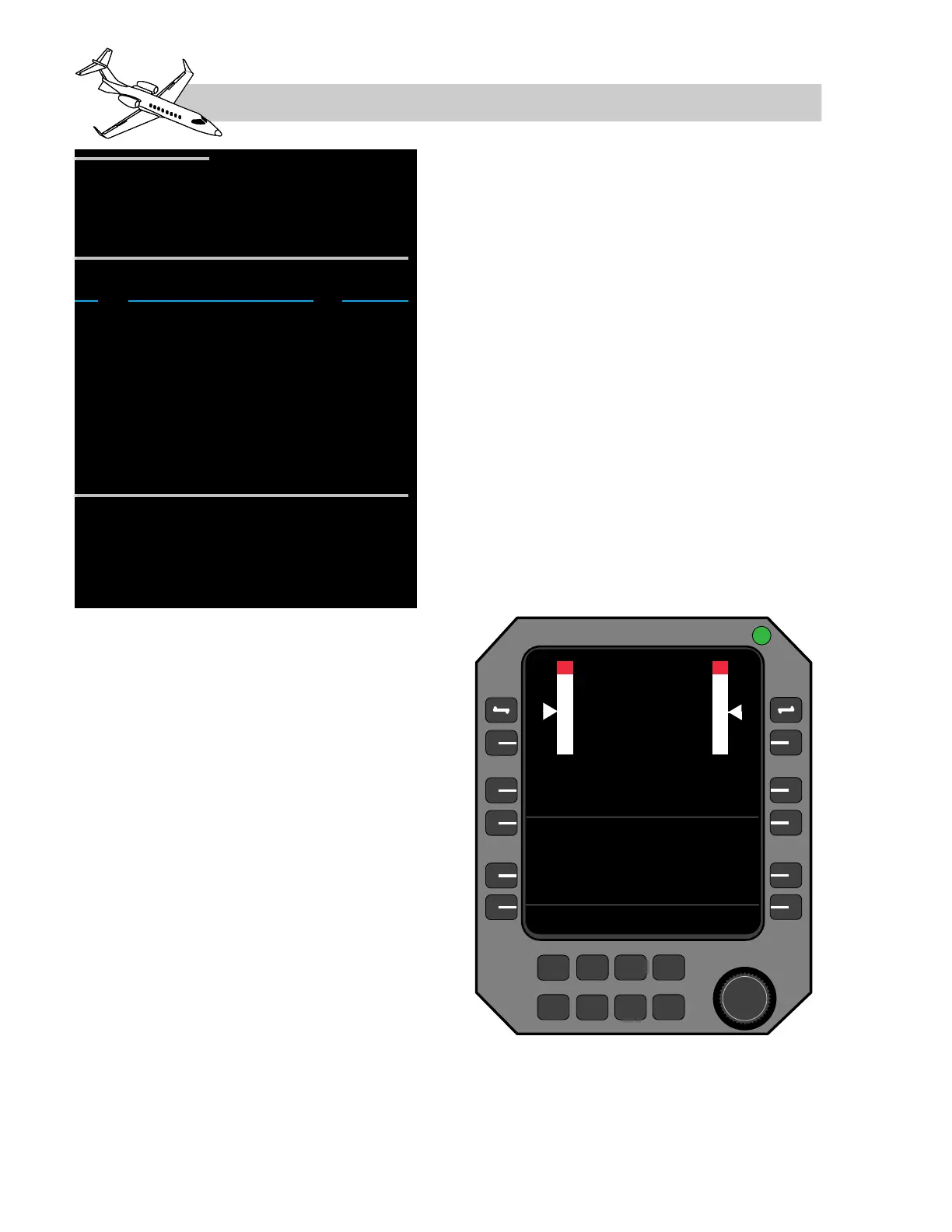
graded display options or reversion proce-
dures, the brake accumulator hydraulic
pressure is also displayed on the RMU backup
engine/system page (Figure 14-21).
On the SUMRY display, brake accumulator
pressure is annotated “B-ACUM.” On the sys-
tem schematic displays available on the EICAS
and MFD (Figure 14-22), brake accumulator
pressure is annunciated in the top right corner
of the schematic and has both a digital read-
out and an analog tape display of brake pres-
sure. On the RMU engine pages, brake
accumulator pressure is annunciated on page
1, to the right of the caption “HYDM-B.”
Main Hydraulic System Failure
In the event of a failure of the main hydraulic
system, the brake source shuttle valve auto-
matically changes the source of hydraulic fluid
flow from the main system to the auxiliary
hydraulic system if the auxiliary hydraulic
system is turned on. With the auxiliary hy-
draulic pump operating, normal braking with
anti-skid protection is available. If the hy-
draulic crossflow valve is open and the fluid
level in the auxiliary hydraulic fluid reser-
voir is low, the hydraulic crossflow valve is au-
tomatically closed, conserving the remaining
hydraulic fluid for the wheel brakes. An amber
CAS message “AUX HYD QTY LO” will also
be displayed in this case.
14-20
FOR TRAINING PURPOSES ONLY
LEARJET 45 PILOT TRAINING MANUAL
FlightSafety
international
LEARJET 45 PILOT TRAINING MANUAL
FlightSafety
international