the CDH can be used to tune COM 1 fre-
quencies while the RMU is being used as a
NAV display.
The navigation display is accessed by de-
pressing the PGE key on the RMU, causing the
PAGE MENU to be displayed (Figure 16-9).
Selecting the NAVIGATION option with the
line select key will then display the navigation
page.
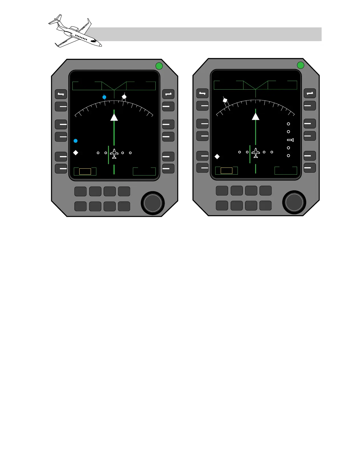
The following information is displayed on the
backup navigation page (Figure 16-16), when
valid data is available:
• NAV (frequency set on #1 NAV receiver,
top left corner)
• ADF (frequency set on #1 ADF, top right
corner)
• CRS (selected course, bottom left corner)
• DME (distance to tuned station, NAV #1,
bottom right corner)
• Bearing pointers for VOR and ADF
• Digital VOR and ADF bearing readouts
(just above CRS)
• “TO/FROM” indication
• Marker beacons
• Heading from #2 AHRS, lubber line and
digital heading readout
• Lateral deviation (VOR and ILS)
• Vertical deviation (GS only)
The navigation displays on both RMUs use
AHRS #2 heading information and NAV in-
formation from NAV1 and ADF1. If the head-
LEARJET 45 PILOT TRAINING MANUAL
16-23
FOR TRAINING PURPOSES ONLY
FlightSafety
international
Figure 16-16. Backup Navigation Display Page on RMU