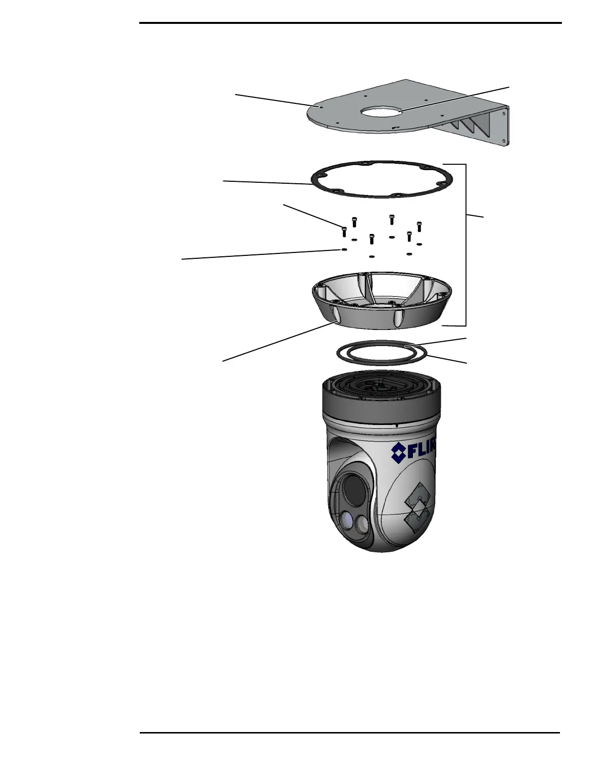
Socket Head Cap Screw with locking patch
M6 X 1.0
Length: 16 mm
316 Stainless Steel
6 places
Apply corrosion inhibitor (USS TEF-GEL)
Torque to 9.5 N-m (7 lb-ft)
AS568-436 EPDM O-Ring
[5.85in ID x .275in DIA]
[49mm ID x 7mm DIA]
AS568-444 EPDM O-Ring
[7.72in ID x .275in DIA]
[96mm ID x 7mm DIA]
M400 Weight: <12.25 kg (27 lb)
Cable Port
Mounting holes per
customer supplied hardware
6 Places
Gasket, Top Down Riser
Top Down Riser
FLIR PN 4141973
Highly recommended
for installations onto
metal surfaces
Fasteners between Top
Down Riser and
mounting surface to be
supplied by the installer.
Warning
Do not bottom fasteners in base.
Bolt length not to exceed 6 mm into base.
Electronics will be damaged by base penetration
Bolt torque not to exceed 9.5N-m (7 lb-ft).
6 places
Washer M6
316 Stainless Steel
6 places
 Loading...