Application examples32
32.4 Insulation deficiencies
32.4.1 General
Insulation deficiencies may result from insulation losing volume over the course of time
and thereby not entirely filling the cavity in a frame wall.
An infrared camera allows you to see these insulation deficiencies because they either
have a different heat conduction property than sections with correctly installed insulation,
and/or show the area where air is penetrating the frame of the building.
When you are inspecting a building, the temperature difference between the inside and
outside should be at least 10°C (18°F). Studs, water pipes, concrete columns, and simi-
lar components may resemble an insulation deficiency in an infrared image. Minor differ-
ences may also occur naturally.
32.4.2 Figure
In the image below, insulation in the roof framing is lacking. Due to the absence of insula-
tion, air has forced its way into the roof structure, which thus takes on a different charac-
teristic appearance in the infrared image.
32.5 Draft
32.5.1 General
Draft can be found under baseboards, around door and window casings, and above ceil-
ing trim. This type of draft is often possible to see with an infrared camera, as a cooler
airstream cools down the surrounding surface.
When you are investigating draft in a house, there should be sub-atmospheric pressure
in the house. Close all doors, windows, and ventilation ducts, and allow the kitchen fan
to run for a while before you take the infrared images.
An infrared image of draft often shows a typical stream pattern. You can see this stream
pattern clearly in the picture below.
Also keep in mind that drafts can be concealed by heat from floor heating circuits.
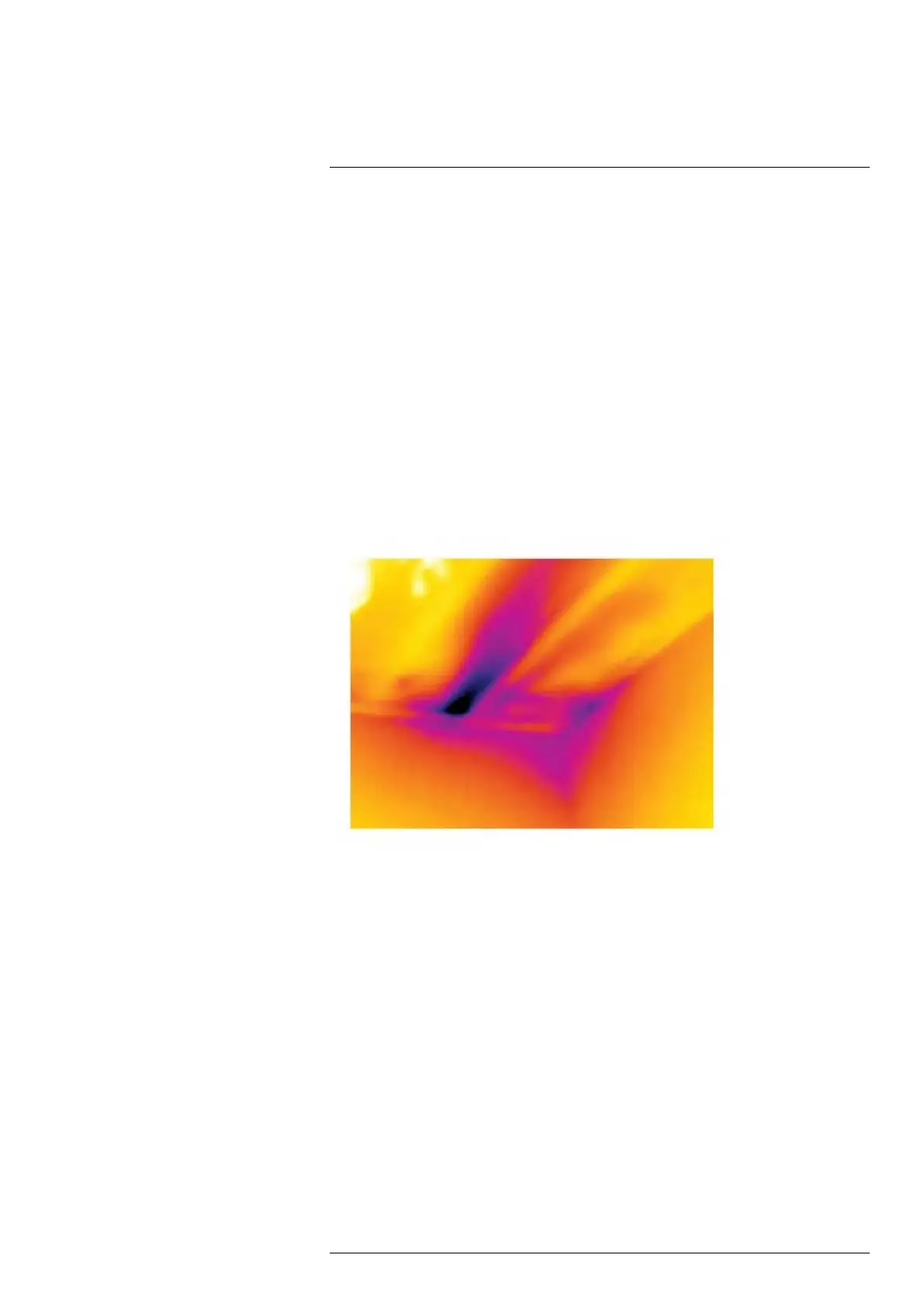
32.5.2 Figure
The image below shows a ceiling hatch where faulty installation has resulted in a strong
draft.
#T559954; r. AP/42311/42335; en-US
204