EasyManuals Logo

FLIR T1020 User Manual

FLIR T1020
260 pages
To Next Page IconTo Next Page
To Previous Page IconTo Previous Page
Page #209 background imageLoading...
Page #209 background image
Digital I/O pin configuration
28
28.1 Pin configuration for the Digital I/O
connector on the HSI box
Pin Function Data
1 IN 1 opto-isolated, 0–1.5 V = low, 3–
25 V = high
2 IN 2 opto-isolated, 0–1.5 V = low, 3–
25 V = high
3
OUT 1 opto-isolated, ON = supply
(max. 100 mA), OFF = open
4
OUT 2 opto-isolated, ON = supply
(max. 100 mA), OFF = open
5
Supply VCC 6–24 VDC, max. 200 mA
6
Supply Gnd Gnd
Note Cables for digital I/O ports should be 100 m (328′) maximum.
#T559954; r. AP/42311/42335; en-US
195
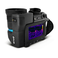
Table of Contents

Other manuals for FLIR T1020

Questions and Answers:

Question and Answer IconNeed help?

Do you have a question about the FLIR T1020 and is the answer not in the manual?

FLIR T1020 Specifications

General IconGeneral
Resolution1024 × 768 pixels
Detector TypeUncooled microbolometer
Digital Camera5 MP
Laser PointerYes
Wi-FiYes
Image Frequency30 Hz
Detector Pitch17 µm
Digital Zoom1-8x continuous
Video RecordingYes
Storage MediaSD card
Spectral Range7.5 – 14 µm
Temperature Range-40 °C to +2000 °C (-40 °F to +3632 °F)
Field of View28° x 21°
Display4.3 in LCD touchscreen, 800 × 480 pixels
FocusMotorized and manual
Image ModesThermal, visual, MSX
Operating Temperature-15 °C to +50 °C
Storage Temperature-40 °C to +70 °C (-40 °F to +158 °F)
ConnectivityUSB 2.0, HDMI
Image StorageJPEG
Image FormatsJPEG
Thermal Sensitivity<20 mK at 30°C

Related product manuals