Calibrator
Performance Tests
33
7. Setup the Quadtech 1865 as follows:
Voltage = 500
Charge Time = 5
Dwell time = 5
Measure time = 20
Discharge time = 5
Mode = Auto
Number of average = 400
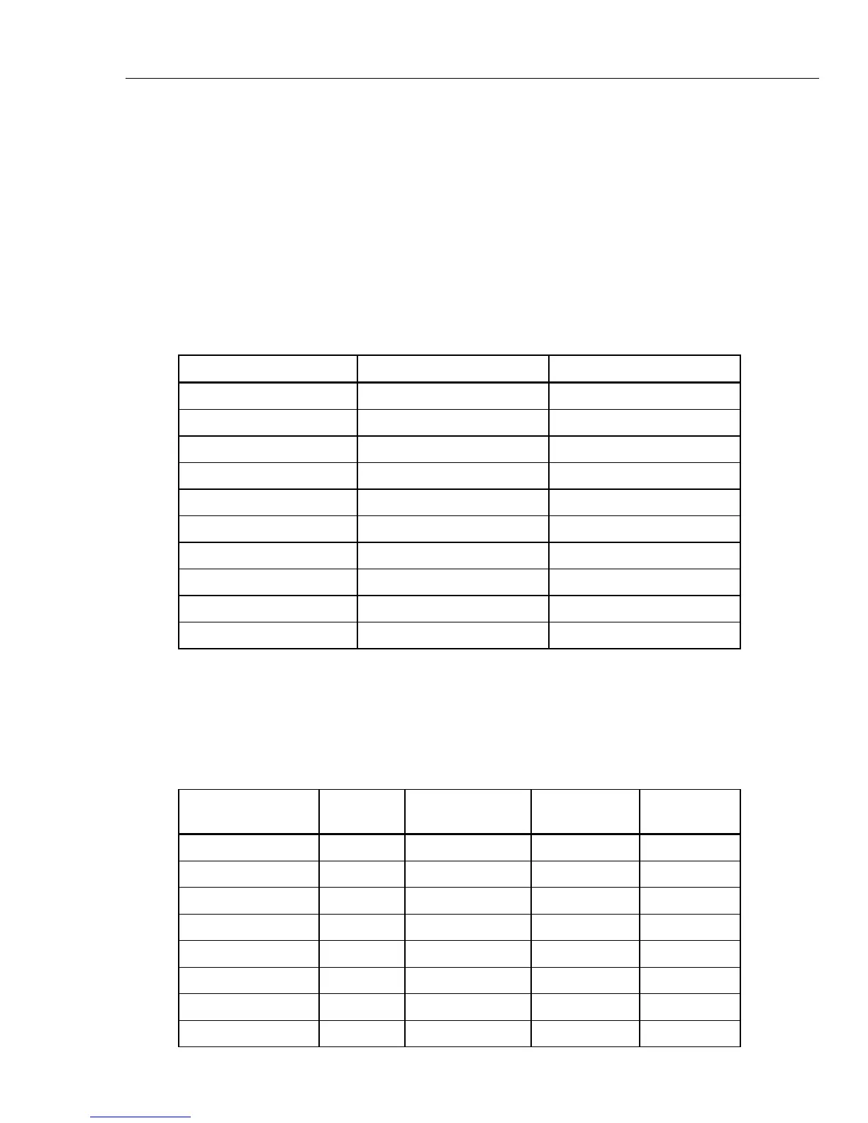
8. Verify the high resistance performance of the Product at the test points in
Table 17. Deviations should not exceed the specified limits. For 18.24 GΩ,
push the MODE softkey until 18G shows in the display.
Table 17. High Resistance Verification
Range Output Tolerance
1.000 GΩ 1.000 GΩ ±0.010 GΩ
1.060 GΩ 1.060 GΩ ±0.011 GΩ
2.000 GΩ 2.000 GΩ ±0.020 GΩ
3.920 GΩ 3.920 GΩ ±0.039 GΩ
5.000 GΩ 5.000 GΩ ±0.050 GΩ
5.370 GΩ 5.370 GΩ ±0.054 GΩ
7.000 GΩ 7.000 GΩ ±0.070 GΩ
7.210 GΩ 7.210 GΩ ±0.072 GΩ
10.000 GΩ 10.000 GΩ ±0.100 GΩ
18.24 GΩ 18.24 GΩ ±0.55 GΩ
Scope Option Verification Tables
Before the 5080A/SC Option leaves the Fluke factory, it is verified to meet its
specifications at the test points shown in Tables 18 through 28. The verification
test points are provided here as a guide when re-verification is desired. Table 42
is a list of test equipment necessary for SC200 Scope option calibration.
Table 18. Voltage Function Verification: AC Voltage into a 1 MΩ Load
Nominal Value (p-p) Frequency
Measured Value
(p-p)
Deviation (mV)
1-Year Spec.
(mV)
5.0 mV 10 Hz
0.11
5.0 mV 100 Hz
0.11
5.0 mV 1 kHz
0.11
5.0 mV 5 kHz
0.11
5.0 mV 10 kHz
0.11
10.0 mV 10 kHz
0.12
20.0 mV 100 Hz
0.15
20.0 mV 1 kHz
0.15