Theory of Operation
Analog Section Detailed Circuit Description 2
2-125
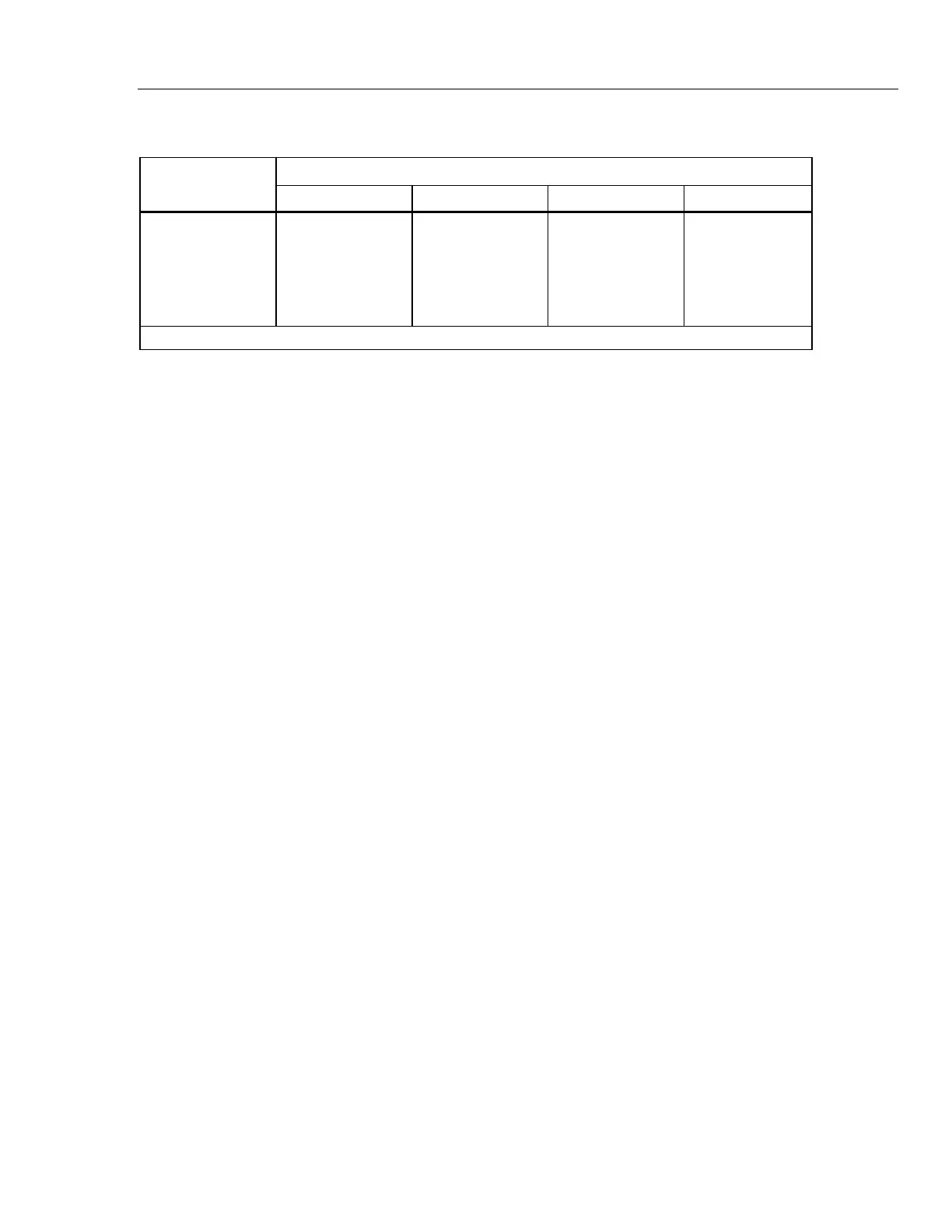
Table 2-15. Relay Settings for Current Range Selection
Relay
Range
220 µA 2.2 mA 22 mA 220 mA
K5 R S S S
K6
R S R R
K7
R S R R
K8
R R S R
K9 R R R S
S=SET R=RESET
2-192. Feedback Loop
The output current develops a 2.2V full-scale voltage across the appropriate shunt
resistors. Buffer amplifiers U2 and U3 isolate the shunt from the remaining feedback
circuit. The negative feedback buffer is op amp U2 configured as a voltage follower. The
positive feedback buffer is made of U3 configured as a voltage follower.
Both the feedback voltage from U2 and U3, and the input voltage from K1 and Q20-Q23
are applied to the precision dual 10:1 matched voltage divider network Z1. Any voltage
difference between the two halves of the network is amplified by the dc amplifier on the
heated substrate hybrid HR2. This amplified dc is applied to the complementary drive
circuit and in turn to the transconductance amplifiers to complete the feedback loop.
Therefore, with a 22V full scale input and the 10:1 divider, the voltage across the shunt
network is forced to 2.2V by the feedback loop. The 2.2V across the shunt is developed
by the full-scale output current on any of the four ranges. By programming the input
voltage over a 10:1 range, the output current follows with a 10:1 range. By switching the
shunt resistors, four 10:1 ranges give a total output range of 20 µA to 220 mA.
2-193. Current Output Switching
Relays K10-K15 switch the output current for the various modes of operation required by
this assembly. When K13 is reset, it switches in a dummy load (R14) to prevent
transients during switching, and also for use during diagnostics. Non-latching relay K15
connects the return lines to the output whenever an output is called for. Non-latching
relay K14 connects the output signal to latching relay K12. Relay K12 switches the
output to the AUX CURRENT OUTPUT binding post while in the reset position, or to
the OUTPUT HI binding post while in the set position.
The four ranges of output current can be connected to the B CUR line by relay K11. B
CUR is routed to the rear-panel 5725A connector. This allows all current ranges to be
available from the binding posts on the 5725A Amplifier if so selected by the operator.
2-194. Generation of the 2.2A Range
To generate the 2.2A range, the Current assembly is set to the 22 mA range with its
output directed to the High Voltage/High Current assembly (A15). This connection is
made via the IHV line by relay K10 in the set position. The High Voltage/High Current
assembly amplifies current by 100 to create the 2.2A range. This high current output is
returned to the Current assembly via the B CUR line. Relay K11 in the set position
directs it to the output relays, K12-K15, of the Current assembly.
During internal calibration of the 2.2A range, the Current assembly is set to the 22 mA or
2.2 mA range and directed to the High Voltage assembly in the same manner as
previously described.