EasyManuals Logo

Fluke 5700A Series User Manual

Fluke 5700A Series
576 pages
To Next Page IconTo Next Page
To Previous Page IconTo Previous Page
Page #280 background imageLoading...
Page #280 background image
5700A/5720A Series II Calibrator
Service Manual
3-70
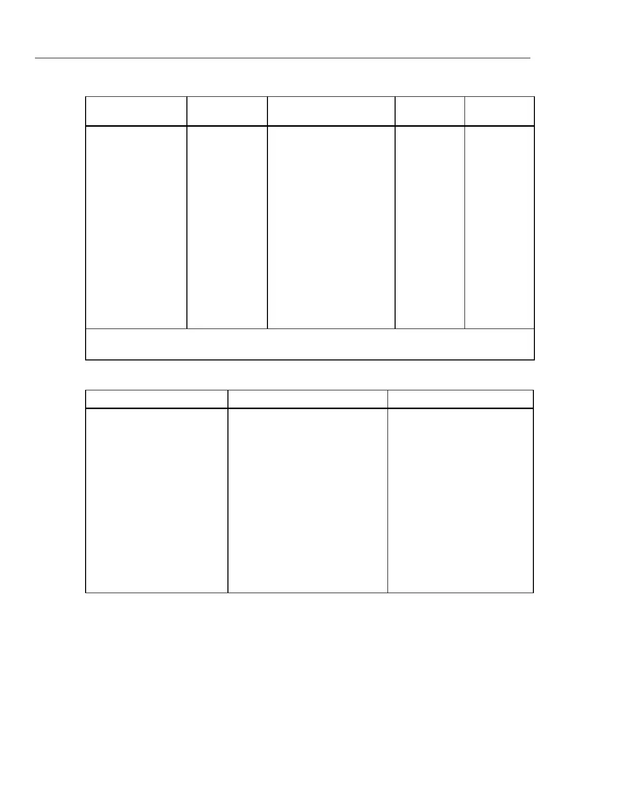
Table 3-37. AC V Distortion Test Summary
5700A/5720A Series
II Output
Load Resistors Frequency Measured
Distortion
Max.
Distortion
2V 100, 1/8W 10 Hz, 20 Hz 0.054%
1 kHz, 20 kHz, 50 kHz, 0.044%
100 kHz, 200 kHz, 500 kHz 0.355%
20V 1 k, 1/2W 10 Hz, 20 Hz 0.0535%
20 kHz, 100 kHz 0.0385%
200 kHz, 500 kHz 0.304%
200V 10 k, 5W 10 Hz, 20 Hz 0.055%
50 kHz, 100 kHz 0.1065%
300V(1) 15 k, 5W 40 Hz 0.1%
300V(1) 15 k, 5W 50 kHz 0.3%
300V(1) 15 k, 5W 70 kHz 0.4%
(1) The 5700A/5720A Series II maximum volt-Hertz product is (2.2 x 10
7
) The 300V level assumes that a
Fluke 5725A Amplifier is attached.
Table 3-38. Test Record for Flatness Check of the AC 2 mV Range
Frequency UUT Error Display Reading Limits
10 Hz
20 Hz ±0.26%
40 Hz
1 kHz ±0.26%
20 kHz ±0.29%
50 kHz ±0.49%
100 kHz ±0.87%
300 kHz
500 kHz ±1.83%
1 MHz

Table of Contents

Questions and Answers:

Question and Answer IconNeed help?

Do you have a question about the Fluke 5700A Series and is the answer not in the manual?

Fluke 5700A Series Specifications

General IconGeneral
TypeMultifunction Calibrator
Operating Temperature0°C to 50°C
Storage Temperature-40°C to 70°C
Humidity10% to 90% non-condensing
Frequency Range10 Hz to 1 MHz
AccuracyVaries by function and range. See manufacturer's specifications for details.
Output StabilityVaries by function and range. See manufacturer's specifications for details.
Power Requirements50 Hz to 60 Hz

Related product manuals