5700A/5720A Series II Calibrator
Service Manual
5-62
4. Check CH1 FLOATING. Connect an oscilloscope to U13 pin 6 (common to TP1).
Set the Calibrator to 6.5V dc, operate, and the oscilloscope to 2V/div at 2 ms/div.
The oscilloscope should display a TTL level signal similar to Figure 5-23. If a failure
is detected, check U13 and its associated components.
5. Check the Clock to U14. Connect an oscilloscope to U10 pin 4 (common= TP3) and
set it for 2V/div at 100 ns/div. Verify it displays a 8 MHz clock similar to Figure 5-
24. If a failure is detected, check U10 and its associated components.
6. Check the Watchdog Clock. Connect an oscilloscope to U14 pin 8(common to TP3)
and verify it displays a TTL level 4 MHz clock. If a failure is detected, check U14.
7. Check the Watchdog Timer. Connect an oscilloscope to U15 pin 13(common to TP3)
and verify it displays a constant logic high. If a failure is detected, check U15 and
associated components.
8. Check the Q1 and Q1* output of U14. Connect an oscilloscope to U14 pin 5
(common to TP3). Set the Calibrator to 6.5V dc, operate, and set the oscilloscope to
2V/div at 2 ms/div. The oscilloscope should display a TTL-level square wave with
approximately a 50% duty cycle. Connect the oscilloscope to pin 6 of U14 and verify
it to be the compliment signal. If either signal is incorrect, U14 is probably at fault.
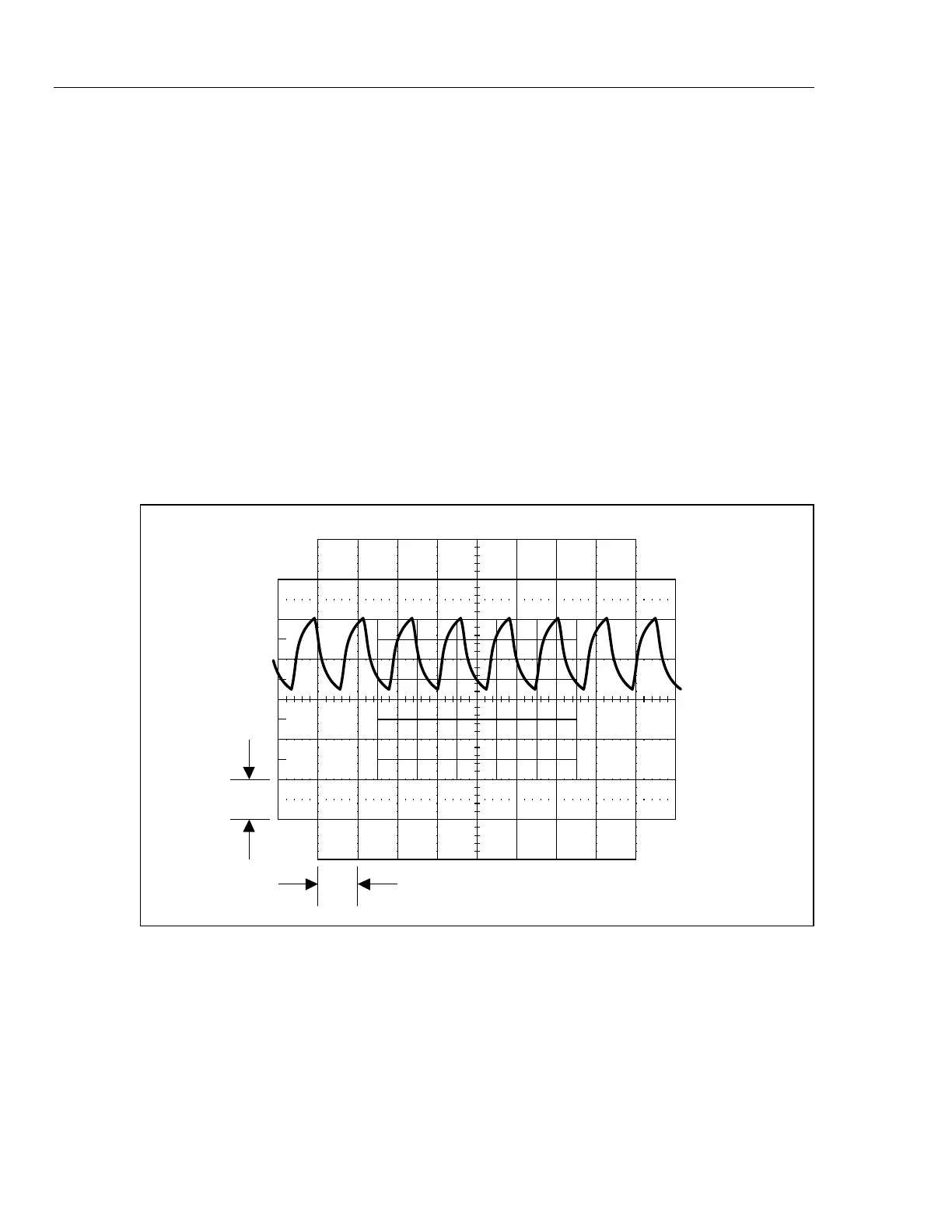
1 V
10 ms
F5-22.EPS
Figure 5-22. Waveform at Pin 10 of U6
9. Check CH1 SHUNT. Connect an oscilloscope to TP6 (common to TP3). Set the
Calibrator to 6.5V dc, operate, and set the oscilloscope to 2V/div at 2 ms/div. The
oscilloscope should display a signal similar to Figure 5-25. If a failure is detected,
check Q35 and its associated components.