Theory of Operation
Digital Section Detailed Circuit Description 2
2-23
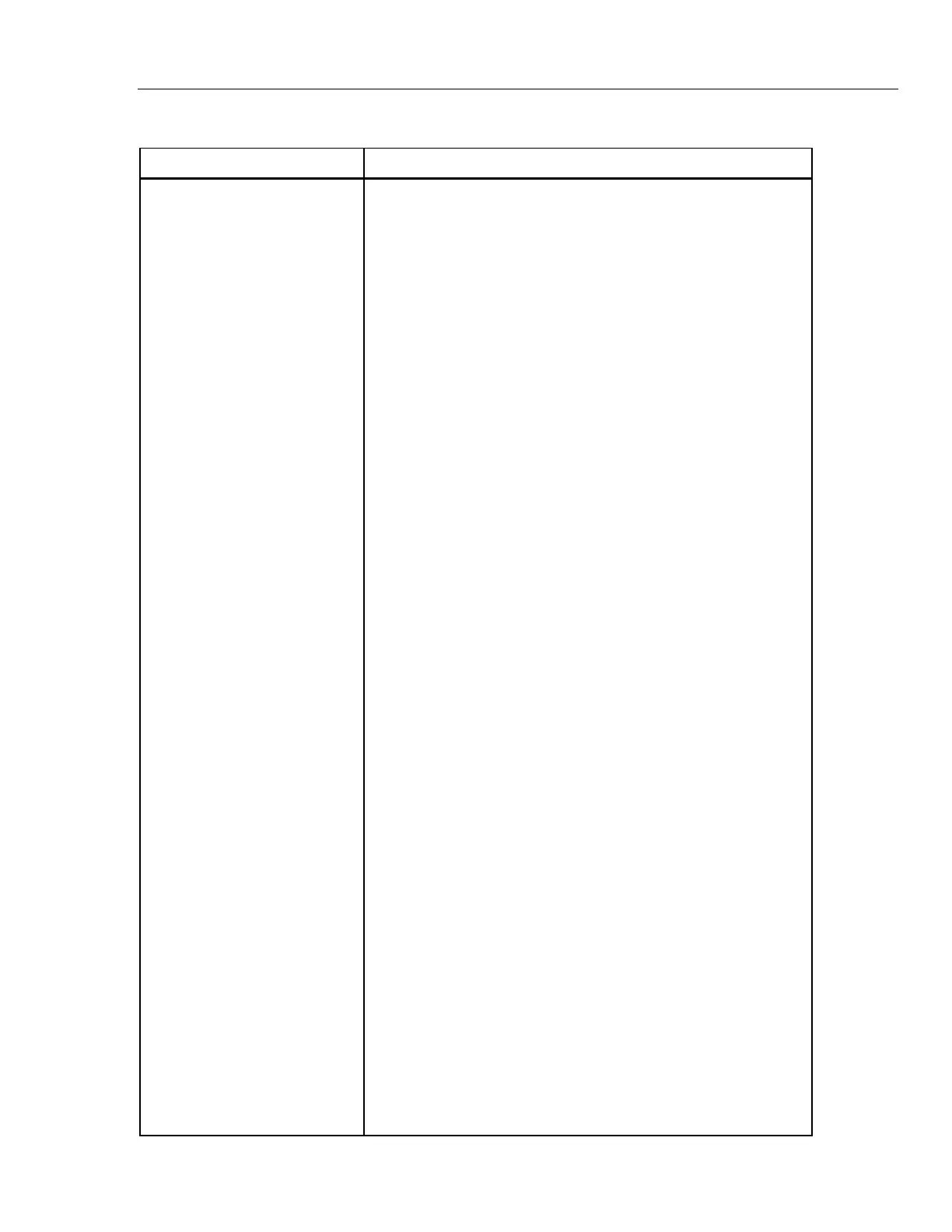
Table 2-3. CPU Acronym Glossary
Signal Name Function
A01-A23 Address lines
ADCLKCS* Clock/calendar (U33) chip select
AS* Address strobe
BERR* Bus error
BGACK* Bus grant acknowledge
BR* Bus request
BRPDRTINT* Rear panel DUART interrupt
BRPDTK* Rear panel data transfer acknowledge
BRPIEEEINT* Rear panel IEEE-488 interrupt
CLKCALINT* Clock/calendar interrupt
D00-D15 Data lines
DOGCLR Dog clear (clears watchdog timer)
DOGINTH Dog interrupt (interrupt from watchdog timer)
DRTDTK* DUART data transfer acknowledge
DTACK* Data transfer acknowledge
E Enable for 6800 family devices (737.28 kHz clock)
EXDUARTINT* External DUART Interru
FAN1 Signal monitoring fan 1
FAN2 Signal monitoring fan 2
FANINT* Fan monitor interrupt
FC0 Function code output 0
FC1 Function code output 1
FC2 Function code output 2
FPDTK* Front panel data transfer acknowledge
FRNTPNLCS* Front panel chip select
FRNTPNLEN* Front panel enable
GCDRTCS* Guard crossing DUART chip select
GCDUARTINT* Guard crossing DUART interrupt
INTRCNTL1 Interrupt control 1
INTRCNTL2 Interrupt control 2
IPL0* Interrupt priority level 0
IPL1* Interrupt priority level 1
IPL2* Interrupt priority level 2
KEYBRDINT* Keyboard interrupt
LDS* Lower data strobe
MISCCS* Miscellaneous chip select enable (upper address bits decoder)
NVMCS* Nonvolatile memory chip select
NVMOE* Nonvolatile memory output enable
PROM0CS* PROM 0 chip select (U15 and U16)
PROM1CS* PROM 1 chip select (U17 and U18)
PROM2CS* PROM 2 chip select (U23 and U24)
PSFAILINT* Power supply fail interrupt
RAM0CS* RAM chip select (U19 and U20)
RAM1CS* RAM chip select (U21 and U22)
RAM2CS* RAM chip select (U40 and U41)
R/WR* Read/write
RDINT* Read interrupt
RDL* Read data lower
RDU* Read data upper
RDY/BSYL Ready/busy
RPSEL* Rear panel chip select
RRPNLEN* Rear panel enable
RXDA Receive Data Port A
RCVB Receive Data Port B
SCLK Serial clock
TXDA Transmit Data Port A
TXDB Transmit Data Port B
UDS* Upper data strobe
WRL* Write lower
WRU* Write upper
XDUARTCS* External DUART chip select