8062A
Instruction Manual
4-26
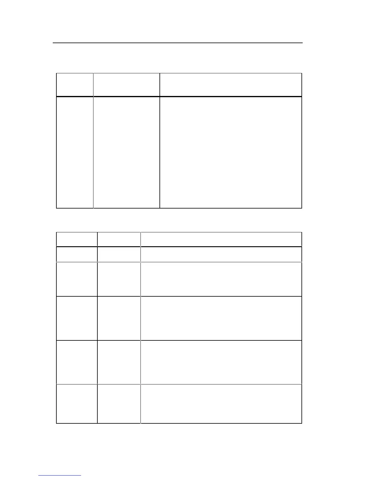
Table 4-7. Troubleshooting the Resistance Function: Voltage Sources
for Ranges
Range
Voltage Source
(±10%)
Comment
200Ω
2 kΩ
20 kΩ
200 kΩ
MΩ
4.5V
1.2V
1.2V
1.2V
2.1V
These values should be obtained when
no external resistors are connected to
the resistance inputs. Measure voltage
between common (J2) and TP10. Note
that the MΩ and 200 kΩ ranges will be
loaded by a 10 MΩ input impedance.
Use a high impedance voltmeter for the
measurement or decrease the voltage
source magnitude appropriately. A DMM
with a 10 MΩ input impedance will read
approximately 1.9V in the MΩ range.
Table 4-8. U3 (MAC) Pin Descriptions
Pin No. Mnemonic Description
1 Tone 2.66 kHz square wave to tone generator.
2
3
4
CFO
CM+
CM-
Output, + input, - input, respectively, of the
continuity function comparator.
5
6
7
VSS
HI
LO
-5.1V supply (externally generated).
Input to the a/d converter.
Sense ground for the a/d converter.
8
9
FC+
FC-
Connections to the “flying capacitor” which
stores the reference voltage applied to the a/d
converter during the read period. Plus and
minus signs indicate polarity of stored voltage.
10
11
COM
VREF+
Analog common.
Input for 1V reference voltage for a/d converter
and power supply.