4-20
FLOW
TS4
24V
OUT
4-20
#2
Red 1
Red2
Yel 3
Wh 4
Wh 5
PULSE
/ALM
TS2
TS1
F1
J1
1
24V, 0.75A
2 3
IN
+1
+1 -2
-2
+3
-4
+5
-6
+7
-8
TS3
REMOTE
SENSOR
4 to 20mA FLOW RATE
4 to 20mA TEMPERATURE
OR FLOW RATE
Customer PLC or DCS
FT3
+
(+)1( )2
+
-
-
TS4
24V
OUT
-
* (see important note below)
* (see important note below)
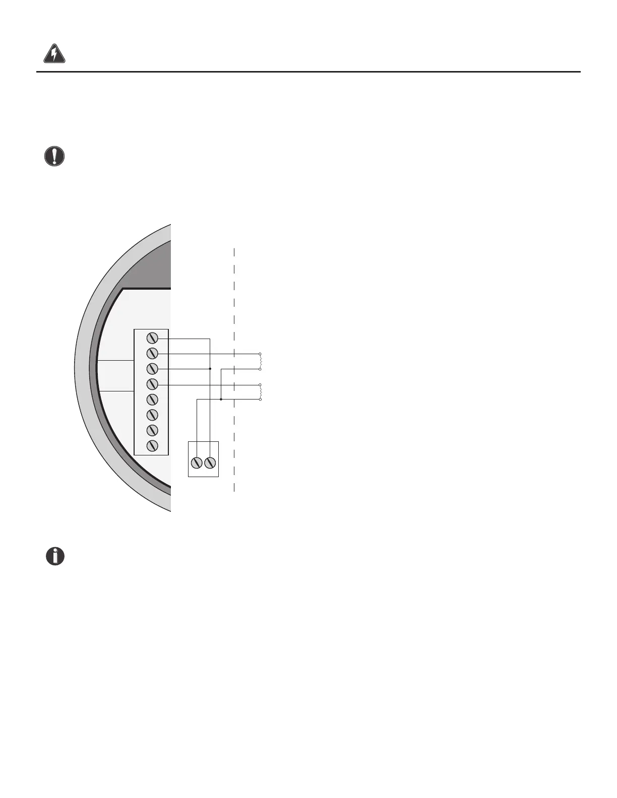
4-20mA Output Wiring: Loop Power Provided by FT3
Bring the 4-20mA wiring in through the right hand conduit opening. Connect the 4-20mA wiring as
shown in the diagram below.
CAUTION! When using the 4-20mA output to control equipment in a failsafe application, see
the wiring conguration on p. 40.
Fig. 3.6: 4-20mA Output Wiring for Loop Power Provided by FT3
NOTE!
• This wiring option is only available with the isolated 24V output power option.
• When using a 12 volt power supply, the load resistor on the 4-20mA output must be
125 ohms or less to operate properly.
• When using 24 volt power, the load resistor is typically 250 ohms. A 250 ohm resistor in
the 4-20mA circuit will result in a 1 to 5 volt signal to the PLC or DCS.
• When using a 24 volt power supply, the load resistor on the 4-20mA output must be
600 ohms or less.
• Some PLC and DCS equipment have built in load resistors, please refer to the technical
manuals of such equipment.
Wiring | 39
Model FT3
Wiring