4-20
FLOW
TS4
24V
OUT
4-20
#2
Red 1
Red2
Yel 3
Wh 4
Wh 5
PULSE
/ALM
TS2
TS1
F1
J2
1
24V, 0.75A
2 3
IN
+1
+1 -2
-2
+3
-4
+5
-6
+7
-8
TS3
REMOTE
SENSOR
+24VDC
4 to 20mA FLOW RATE
24VDC Return
Customer PLC or DCSFT3
21 mA
20 mA
4 mA
3.6 mA
0 mA
NAMUR
Alarm
Range
NAMUR
Alarm
Range
Working Range
Normal Operation
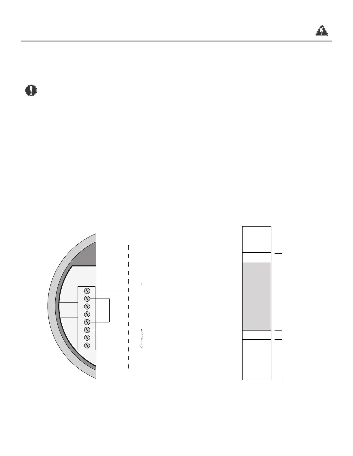
Setting Up the NE-43 Alarms
The FT3 ow meter supports the NAMUR specication NE-43 for alarms on the 4-20mA output. See p.
55 for the 4-20mA ouput NAMUR operation.
CAUTION! Congure the FT3 with the following setup when using the 4-20mA output to
control equipment in a failsafe application.
4-20mA Failsafe Wiring: NAMUR NE-43
When the 4-20mA output is used to control equipment in failsafe applications:
• Wire the 4-20mA output in series with the Alarm output as shown in Fig. 3.7.
• Congure the Pulse/Alarm output to Alarm and select System Alarm as shown in the "Alarm
Output" on Page 58.
The System Alarm output is designed to allow current to ow during normal operation and interrupts
current when power to the meter is lost or in a System Alarm condition.
In the 4-20mA Failsafe Wiring conguration of Fig. 3.7, the 4-20mA signal goes to 0mA if power to
the FT3 is lost or a System Alarm occurs.
Fig. 3.7: 4-20mA Failsafe Wiring and Range of 4-20mA Output for NAMUR Alarm
Wiring | 40
Model FT3
Wiring