4-20
FLOW
TS4
24V
OUT
4-20
#2
Red 1
Red2
Yel 3
Wh 4
Wh 5
PULSE
/ALM
TS2
TS1
F1
J1
1
24V, 0.75A
2 3
IN
+1
+1 -2
-2
+3
-4
+5
-6
+7
-8
TS3
REMOTE
SENSOR
+24VDC
24VDC Return
2.4K to 10K OHM
Frequency or Alarm Output
Customer PLC or DCS
FT3
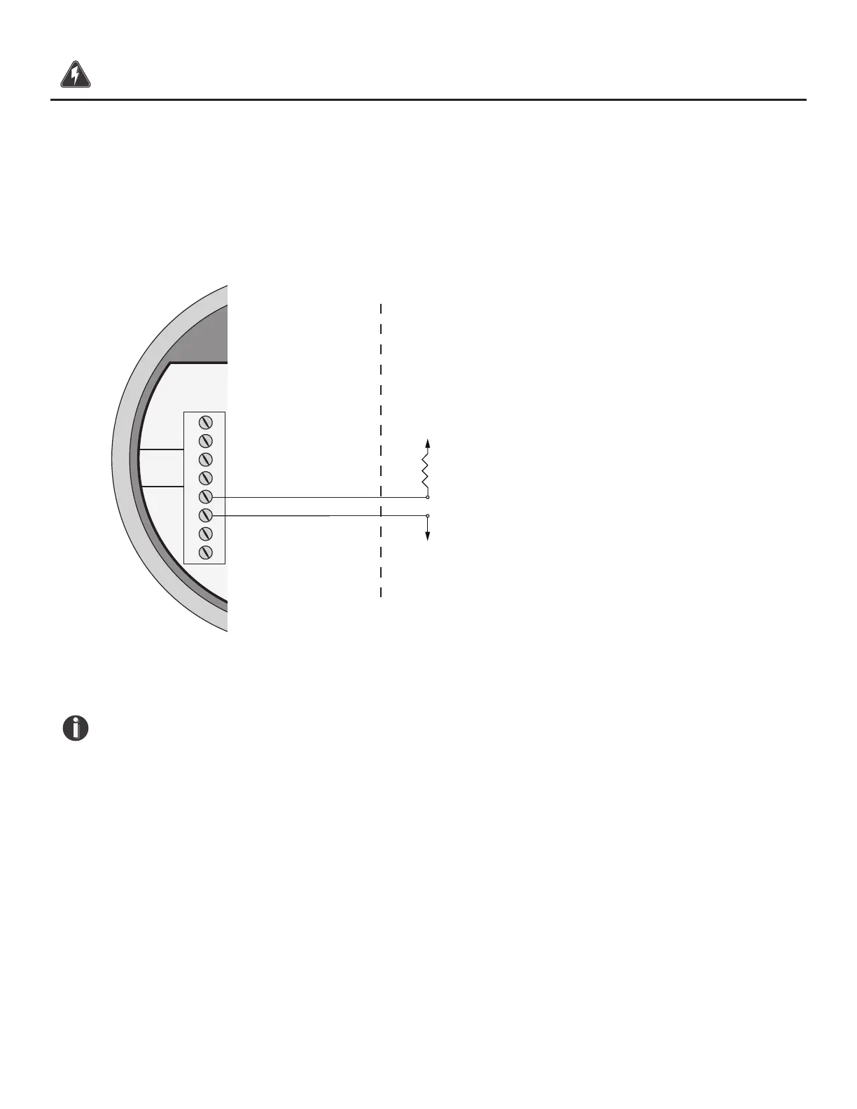
Pulse/Alarm Output Wiring
Bring pulse/alarm wiring in through the right-hand conduit opening. Connect to TS2, 5(+) and 6(-).
The pulse/alarm output is an open collector circuit capable of sinking a maximum of 20mA of current.
Pulse or Alarm selection is programmed using the display. Only one option, pulse or alarm, can be
active at a time.
Fig. 3.8: Pulse/Alarm Output Isolated (Recommended)
NOTE!
• The FT3 Pulse/Alarm output is typically used to drive digital circuitry or solid-
state relays. The output of a solid state relay may, in turn, operate loads such as
electromechanical relays or alarm indicators.
• The maximum load current of the Pulse/Alarm output is 20mA. Choose a load
resistance that provides approximately 10mA with the power supply operating voltage.
• When the output is congured for Alarm and an alarm is not active, the output
will be on (0 volts output). When an alarm is active, the output will be o
(24 volts output).
Wiring | 41
Model FT3
Wiring