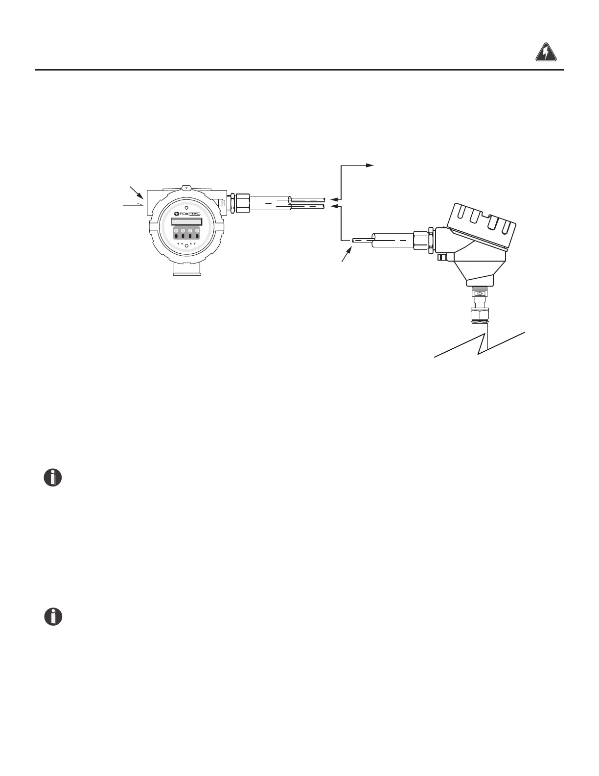
2X 3/4 " NPT,
Female
Remote Cable, 5 Conductor,
Shielded, 100ft (30.48m) Max.
F1 F2
F3 F4
Input
Power
Signal Wiring
Remote Wiring
Remote wiring is only necessary when the remote sensor option has been ordered.
Fig. 3.15: Remote Wiring
Five wire shielded cable required. The shielded cable should be run through a separate grounded
steel conduit (no other cables or wires in the conduit). If you are using your own cable, make sure
that the cable length does not exceed 100 feet and has a wire resistance that does not exceed one
ohm (18 AWG recommended).
NOTE! Do not connect the cable shield at the electronics enclosure end. Connect the cable
shield at the remote sensor terminal.
NOTE! The enclosures must be properly grounded with a quality earth ground. 16 gauge,
stranded wire is recommended.
Use an extension cable to connect the terminals of the remote sensor enclosure to connector TS3
located behind the rear cap of the electronics enclosure as shown in Fig. 3.16 and Table 3.1 on the
following page.
NOTE!
Serial numbers:
If you have more than one meter, you must ensure that the serial
numbers of the probe/remote enclosure, electronics enclosure, and ow body match one
another. These items have been manufactured and calibrated to operate as a unit and cannot
be mismatched.
Wiring | 48
Model FT3
Wiring