FLOW
10X Pipe ID
Proper
Profile
15X Pipe ID
F1 F2
F3 F4
FLOW
4X Pipe ID
Proper
Profile
8X Pipe ID
F1 F2
F3 F4
INLINE
Branch Outlet
(installed by
customer)
Irregular
Profile
Irregular
Profile
FC20 Flow Conditioner
installed between two flanges
Proper
Flow
Profile
Irregular Flow
Profile
Branch Outlet
(installed by customer)
FLOW
5X Pipe ID min.
2 x
Pipe ID
5X Pipe ID min.
INSERTION WITH FC20
F1 F2
F3 F4
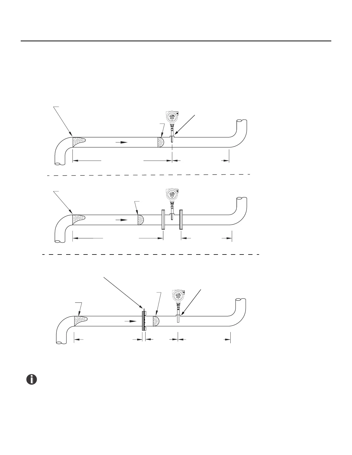
Instructions for Flow Meter Lateral Placement
Install the model FT3 ow meter so that it is far enough away from bends in the pipe, obstructions, or
changes in line sizes to ensure a consistent ow prole. See Fig. 2.1 below for your meter type.
Fig. 2.1: Upstream and Downstream Pipe IDs for Insertion and Inline Flow Meters
NOTE!
• Pipe ID = Inside Diameter
• The probe diameter is ½"
• An irregular ow prole will aect sensor accuracy
• See FC20 Installation Instructions (PN 109193) for more information
Installation | 21
Model FT3
Installation