4-20
FLOW
TS4
24V
OUT
4-20
#2
Red 1
Red2
Yel 3
Wh 4
Wh 5
PULSE
/ALM
TS2
TS1
F1
J1
1
24V, 0.75A
2 3
IN
+1
+1 -2
-2
+3
-4
+5
-6
+7
-8
TS3
REMOTE
SENSOR
2.4K to 10K OHM
Frequency or Alarm Output
Customer PLC or DCS
FT3
+
(-)2
(+)1
TS4
24V
OUT
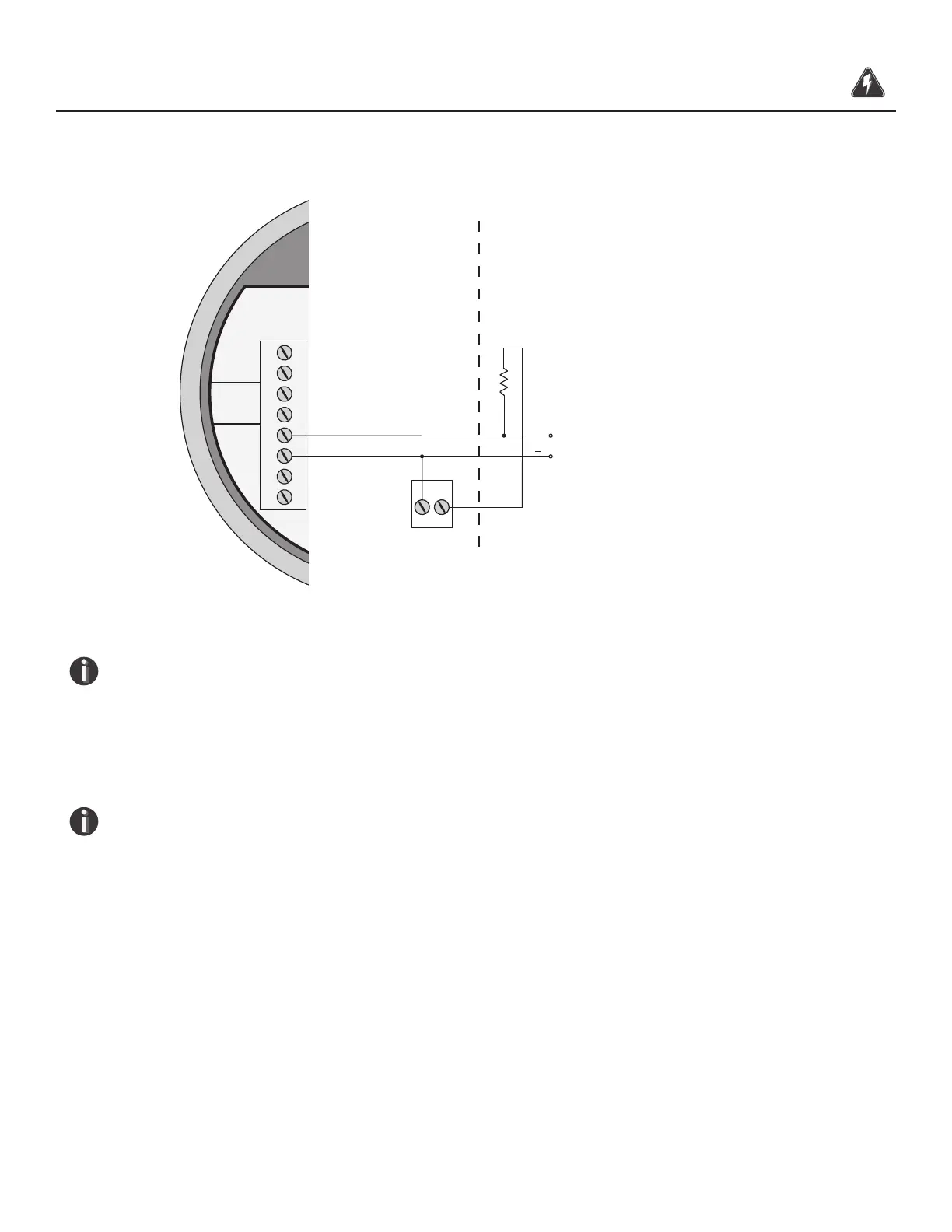
Fig. 3.9: Pulse/Alarm Output Local +24V Power Option
CAUTION!
Do not exceed 42 mA total load on the 24V Output TS4 (ie including 4-20mA outputs).
NOTE!
• This wiring option is only available with the isolated 24V output power option.
• The FT3 Pulse/Alarm output is typically used to drive digital circuitry or solid-
state relays. The output of a solid state relay may, in turn, operate loads such as
electromechanical relays or alarm indicators.
• The maximum load current of the Pulse/Alarm output is 20mA. Choose a load
resistance that provides approximately 10mA with the power supply operating voltage.
• When the output is congured for Alarm and an alarm is not active, the output
will be on (0 volts output). When an alarm is active, the output will be o
(24 volts output).
Wiring | 42
Model FT3
Wiring